Quick Answer: A bearing size chart is a reference table that lists boundary dimensions for a bearing designation, usually bore diameter, outside diameter, and width or assembly width. It helps you compare envelope sizes, but it does not by itself confirm load rating, tolerance, clearance, or interchangeability. Use the chart to narrow the search, then verify the exact row, suffix, unit, and standard revision in the manufacturer’s datasheet before ordering.
A bearing size chart is most useful when you treat it as a screening tool, not a final answer. The chart tells you whether a bearing can fit the available space; the datasheet and application check tell you whether it belongs there. This guide explains the columns, the reading sequence, the common bearing families, and the points where a size match stops being enough.
What a Bearing Size Chart Includes
A bearing size chart is built around a small set of boundary dimensions. The usual columns are bearing designation, bore diameter (d), outside diameter (D), and width (B) or assembly width (T). Many charts also show bearing type or series, the unit of measure, and a notes column for suffixes or special features.
Boundary dimensions are not the same as performance data. Load ratings, speed ratings, tolerance class, internal clearance, and lubrication details may appear in a technical datasheet, but they are not the core size-chart data. Use the chart to check envelope size, then use the datasheet to check the bearing’s working limits.
Charts may be metric, inch, or mixed. Mixed tables are workable when every column has a clear unit label. Some charts list envelope dimensions and omit chamfer, fillet, or suffix details, so confirm the chart source and standard revision before you rely on a row.
How to Read a Bearing Size Chart
Read a chart in a fixed order so you do not match the wrong row. First read the designation, then locate the series block, then match bore diameter, outside diameter, and width or assembly width. A dimension match is a starting point; the bearing type, series, and suffix notes must also agree.
- Read the full bearing designation, including prefixes and suffixes.
- Locate the correct bearing type and series block.
- Match bore diameter (d), then outside diameter (D), then width (B) or assembly width (T or C).
- Check the notes for seals, shields, snap rings, clearance, tolerance, or other suffixes.
Similar designations can have different widths, seal or shield profiles, snap-ring grooves, or tolerances. Use the chart that belongs to the same bearing type and standard as the bearing you are checking. A dimensional match alone does not guarantee functional interchangeability.
Metric Bearing Size Charts by Common Bearing Type
Metric charts are commonly organized by bearing family and series. Filter by bearing type before you compare dimensions. A deep groove ball bearing row and a cylindrical roller bearing row may share a nominal bore but differ in outside diameter, width, internal design, and load behavior.
Common metric families include:
- Deep groove ball bearings
- Angular contact ball bearings
- Self-aligning ball bearings
- Cylindrical roller bearings
- Spherical roller bearings
- Needle roller bearings
- Tapered roller bearings
- Thrust bearings
Metric boundary dimensions are usually given in millimeters. Some metric-designated bearings use inch dimensions or special envelopes, so verify the datasheet when the designation or application is unusual. Do not compare across bearing families by bore size alone.
Deep Groove Ball Bearing Size Charts (60/62/63/64 Series)
The 60, 62, 63, and 64 series are common deep groove ball bearing series. They differ in the relationship between bore, outside diameter, and width, so the same bore can appear in more than one series with a different envelope. Locate a bearing by bore size and series, then confirm the row against the full designation.
Seals, shields, snap rings, and clearance suffixes may require separate datasheet rows or notes. A 2RS or ZZ suffix can change the width or outside profile; an NR suffix can add a snap-ring groove. Use manufacturer-specific rows for suffix variants rather than assuming the base row applies.
Miniature deep groove ball bearings may follow inch or special metric series and may not fit standard 60/62/63/64 tables. Check the datasheet when the bearing is very small or the designation is non-standard.
Tapered Roller Bearing Size Charts (Metric)
Metric tapered roller bearing charts use several width symbols. T is the total assembly width, B is the inner-ring width, and C is the outer-ring width. A chart may list a complete bearing or separate cup and cone components, so read the column heading and the notes before you compare values.
Tapered roller bearings also need axial clearance and mounting dimensions that a basic size row may not show. Those values belong in the technical datasheet or the application drawing. Metric tapered roller bearing charts may include standard series and manufacturer-specific series. Do not use a radial deep groove ball bearing chart for a tapered roller bearing.
Inch tapered roller bearings require inch charts or separate tables. Do not convert an inch row to metric and assume the result is a standard metric bearing.
Cylindrical, Spherical, and Needle Roller Bearing Size Charts
Roller bearing charts include boundary dimensions and sometimes additional width or rib details. Cylindrical roller bearings can have different flange arrangements and cage designs, so the same bore and outside diameter may not describe the same internal geometry. Check the designation and the chart notes for the specific variant.
Depending on the bearing type, a chart may list d, D, B, F, E, or assembly width. Needle roller bearings may be drawn-cup, machined-ring, or needle-and-cage assemblies, and those types use different dimension conventions. Needle roller complement dimensions may require separate tables.
Use the chart for the specific roller bearing subtype, not just the nominal bore. Needle roller bearings without inner rings may be matched to shaft dimensions rather than a standard bore. Confirm the subtype before you compare any row.
Thrust Bearing Size Charts
Thrust bearing charts list bore, outside diameter, height, and sometimes washer or housing-washer dimensions. Common symbols include d, D, H, d1, and D1. The height symbol is especially important because a thrust bearing must fit the available axial space.
Distinguish thrust ball, cylindrical roller thrust, spherical roller thrust, and needle roller thrust bearings. They have different washer and cage arrangements, and their mounting height and washer thickness must be checked separately. Use thrust-specific charts; radial bearing charts are not interchangeable.
Some thrust bearing assemblies use non-standard height or washer combinations. Check the datasheet when the mounting space is fixed or the original bearing has been replaced before.
Inch, Miniature, and Flanged Bearing Size Charts
Inch and miniature bearing charts may use inch dimensions, decimal inches, or mixed metric-inch designations. Flanged bearings can add flange diameter and flange width as separate columns. Confirm the unit label before you compare an inch row with a metric row.
Flange dimensions may include flange outside diameter, flange width, and overall width. Miniature bearing numbering systems are not universal across manufacturers. Two bearings with similar miniature designations may have different bore, outside diameter, or width conventions.
Some miniature bearings are named by inch bore but use metric outside dimensions, or the reverse. Verify the datasheet when the designation is miniature, flanged, or mixed-unit.
Bearing Number vs. Size Chart
Some bearing numbers encode bore size, but the coding system is not universal. A designation may also carry prefixes and suffixes that identify bearing type, series, seals, shields, clearance, tolerance, or special features. The number is an identity code, not a complete size specification.
Cross-referencing by bearing number alone can produce dimensional or performance mismatches. Use the original manufacturer’s designation system when decoding a bearing number, and check the suffix meanings because they may vary by manufacturer. Obsolete, private-label, and custom designations may not follow common numbering rules.
When the marking is incomplete or the number is unknown, measure the bearing and compare the result with a datasheet. Do not infer interchangeability from a number that only looks similar.
Tolerances, Clearance, and Suffixes in Bearing Size Charts
Size charts usually give nominal boundary dimensions, not tolerance class or internal clearance. A row can tell you the nominal bore, outside diameter, and width, but it may not tell you whether the bearing is made to a precision tolerance or a specific clearance group. Check tolerance and clearance separately when the application requires a precision fit or controlled internal clearance.
Seals, shields, snap rings, and special suffixes can change width, outside profile, or row selection. Snap-ring grooves and shield or seal dimensions may need their own columns or notes. Use suffix-specific datasheet pages when they are available.
Some suffixes do not change boundary dimensions but do change internal design or performance. A clearance suffix, for example, can change the internal clearance without changing the envelope. Do not assume that an unchanged boundary dimension means an unchanged bearing.
Unit Conversion for Bearing Dimensions
For chart comparison, use 1 inch = 25.4 mm. Convert in one direction, keep enough decimal places to distinguish nearby sizes, and avoid rounding a converted value until after you have compared it with the chart. Rounding too early can create a false match.
Use the original unit for ordering and inspection. If the bearing is specified in inches, order in inches; if it is specified in millimeters, order in millimeters. A converted value is a reference, not a new nominal size. Do not assume exact metric-inch equivalence unless the datasheet states it.
When a chart mixes units, label every column and note the conversion basis. That prevents a decimal-inch value from being read as a millimeter value.
How to Measure and Confirm Bearing Size Before Ordering
Measure a clean, undamaged bearing with suitable calipers or micrometers. Record bore diameter, outside diameter, and width. For flanged or snap-ring bearings, also record flange diameter, flange width, and groove position where relevant. Check the bearing markings, shaft diameter, housing bore, and available mounting space.
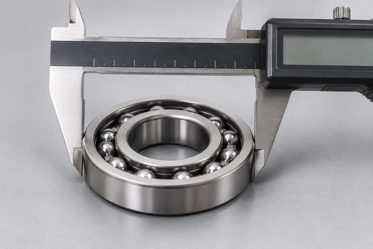
Confirm the measured size against a manufacturer datasheet or an authoritative chart before ordering. A measurement is a cross-check; the datasheet is the specification. If the bearing is worn, corroded, or damaged, it may not give reliable nominal dimensions. Use the shaft and housing measurements as cross-checks.
Do not order from a measurement alone when the bearing has a suffix, a flanged outer ring, or a special width. The suffix can change the fit even when the main envelope looks correct.
Quick-Reference Bearing Size Chart Layout
A useful quick-reference layout shows the unit label, bearing type, series, designation, d, D, and B/T/C, followed by flange or special notes. Every table should state its source standard or revision. If the chart is simplified, say so and list the dimensions it omits.
Use separate tables or filters for metric, inch, miniature, and tapered roller bearings. That prevents a reader from comparing rows that belong to different dimension systems. A downloadable or printable chart is useful when the data is verified and versioned.
Do not present unsourced dimensions as authoritative. A clean layout cannot fix an unverified row.
Limitations: When a Bearing Size Chart Is Not Enough
Boundary dimensions alone do not determine load capacity, speed, life, fit, or interchangeability. A bearing that fits the space may still be unsuitable for the load, speed, temperature, lubrication, or mounting conditions. Load ratings, speed ratings, fatigue life, lubrication, and fit belong in the technical datasheet or an engineering review.
Use a datasheet or engineering review for safety-critical, high-speed, high-load, or precision applications. Also check the application conditions and mounting design for critical equipment. A size chart is a screening tool, not a release-to-service approval.
Non-standard, custom, thin-section, linear, and housed bearing units may not appear in a standard size chart, and obsolete or damaged bearings may not be resolvable from one alone. In those cases, measure the interface and consult the original specification.
Sources and Verification Note
Exact bearing dimensions should be verified against the relevant standard or the bearing manufacturer’s datasheet. Check the standard revision and the bearing suffix before you use any chart. A chart is only as reliable as the source and revision behind it.
For metric radial rolling bearings, ISO 15 is a commonly referenced standard for boundary dimensions. ISO 104 covers boundary dimensions for thrust bearings, and ISO 355 covers tapered roller bearings. Other bearing types and inch series may follow different standards or manufacturer-specific tables. Cite the standards and data that were actually used to compile the chart, and do not claim that a standard covers a bearing type unless that coverage is verified.
If a supplier publishes its own size chart, the chart should carry a source-verification note, the revision date, and the unit basis so buyers can check it against the datasheet.
Conclusion
A bearing size chart is a fast way to screen bore, outside diameter, and width, but it is not a substitute for the datasheet. Read the designation, series, suffix, and unit first; then confirm the exact row against the manufacturer’s data or the applicable standard. Use the chart to narrow the search and the datasheet to make the decision. For critical equipment, verify load, speed, clearance, and mounting conditions before you order.
FAQs
Q1: What do d, D, and B mean in a bearing size chart?
A: d is the bore diameter, D is the outside diameter, and B is the width. For tapered roller bearings, T may be used for the total assembly width and C for the outer-ring width. Check the chart legend because symbols can vary by bearing type.
Q2: How do I find a bearing size from a bearing number?
A: Start with the full designation, including prefixes and suffixes, then use the original manufacturer’s data to decode the type, series, and bore code. Some numbers encode bore size, but the system is not universal. Confirm the exact row in a datasheet before ordering.
Q3: Are bearing size charts in millimeters or inches?
A: They can be in either unit, and some charts mix both. Check the unit label on every column. Metric charts usually use millimeters; inch charts may use inches or decimal inches. Convert only for comparison and order in the original unit.
Q4: What is the difference between B and T in tapered roller bearing charts?
A: B is the inner-ring width, while T is the total assembly width. C is the outer-ring width. A complete bearing row may use T, while separate cup and cone rows may use B and C. Read the column heading and notes before comparing values.
Q5: Can I replace a bearing if the bore, outside diameter, and width match?
A: Not automatically. A dimension match does not confirm load rating, speed capability, internal clearance, tolerance, seal or shield design, or mounting fit. Use the datasheet and the application requirements to confirm interchangeability before replacement.
Q6: Do seals, shields, or snap rings change bearing dimensions?
A: They can. Seals and shields may change the width or outside profile, and a snap-ring groove adds a feature that may need its own column or note. Use the suffix-specific datasheet row rather than the base row.
Q7: How do I measure a bearing if the markings are unreadable?
A: Measure bore, outside diameter, and width with calipers or micrometers, and record flange or groove dimensions if present. Check the shaft and housing as cross-checks. Then compare the measurements with a manufacturer datasheet. A worn or damaged bearing may not give reliable nominal dimensions.
Q8: Where can I find a bearing size chart PDF?
A: Use the bearing manufacturer’s official datasheet or a controlled technical reference, and check the revision date and unit basis. A chart from an unverified source should be treated as a starting point. Confirm the exact row before you order.