Quick Answer: Gears are made by first defining the tooth geometry and material, preparing a blank, then cutting, forming, molding, or printing the teeth. Common metal gear routes include hobbing, shaping, milling, and broaching, followed by heat treatment and finishing when the application needs higher strength or accuracy. The right route depends on gear type, size, material, precision grade, volume, and tooling budget. Final inspection checks tooth profile, lead, pitch, runout, and fit.
Gear manufacturing is not a single machine or a single pass. It is a chain of decisions that starts with the drawing, continues through blank preparation and tooth generation, and ends with heat treatment, finishing, and inspection. The same gear shape can be produced by several routes, but those routes differ in accuracy, tooling cost, cycle time, and the material they handle well.
Buyers and engineers often ask how gears are made because the answer affects price, lead time, and risk. A gear that is adequate for a low-speed prototype may be unsuitable for a loaded transmission. The sections below explain the common methods and the points that should be fixed before a quote or production order.
The Gear Manufacturing Process at a Glance
A typical metal gear moves through these stages:
- Design and specification: define the tooth geometry, quality grade, material, heat treatment, and inspection requirements.
- Blank preparation: turn, bore, face, and pre-machine the body that will carry the teeth.
- Tooth generation: cut, form, mold, or print the teeth by a method suited to the gear type and volume.
- Heat treatment: harden the gear when wear resistance, fatigue strength, or load capacity requires it.
- Finishing: grind, shave, hone, lap, deburr, or coat the gear to reach the final accuracy and surface condition.
- Inspection: check profile, lead, pitch, runout, tooth thickness, backlash, bore, hardness, and surface finish.
- Packing: clean, protect, and package the finished gear for storage or shipment.
Not every gear needs every step. A simple, low-precision gear may be cut and deburred without hard finishing. A plastic molded gear does not receive the same heat treatment as a steel gear. Cast, forged, and powder metallurgy gears often start with a near-net shape, so the sequence shifts toward machining only where the teeth or critical surfaces need accuracy. The sequence described here applies to metal and plastic gears in general industrial applications; specialized gears may add cleaning, coating, balancing, or traceability steps.
Prototype work is different from production. Very small batches may use milling or additive manufacturing to avoid production tooling. The trade-off is usually higher per-part cost, longer manual work, or lower fatigue performance than a mature production process.
Gear Design and Specification Before Manufacturing
A custom gear needs a drawing or a complete specification before quoting and production. The minimum information usually includes:
- Tooth geometry: module or diametral pitch, number of teeth, pressure angle, helix angle, tooth profile, and face width.
- Body and mounting: bore, keyway, hub, shoulder, set screw or clamp features, and overall dimensions.
- Quality: pitch deviation, profile deviation, lead deviation, runout, backlash, and the required gear quality grade.
- Material and treatment: material grade, heat treatment, surface hardness, coating, and any marking or traceability requirement.
Tolerance requirements should be tied to the drawing, not left to a generic statement. Gear accuracy is commonly specified using ISO, AGMA, DIN, or JIS precision grades; the exact grade definition comes from the applicable standard and the drawing. A tighter grade can change the manufacturing route from cutting to grinding or another hard-finishing process.
Design choices limit the process window. High precision usually requires grinding or hard finishing. Internal gears often require shaping or broaching. Material and heat treatment should be fixed early because they affect cutting, distortion, and finishing.
Choosing the Right Material for the Gear
Material selection is a load, speed, and environment decision, not a catalog preference. Common gear materials include:
- Carbon and alloy steel: widely used for loaded gears and available in cut, forged, or heat-treated forms.
- Stainless steel: considered when corrosion resistance matters, with the trade-off of cost and machinability.
- Cast iron: used for larger gears and housings where damping and cost matter more than high strength.
- Bronze and brass: used in worm gears, bushings, and applications where sliding contact or corrosion resistance is important.
- Aluminum: light but lower in strength and wear resistance than steel for many gear duties.
- Engineering plastics: used for low-load, low-noise, and lubrication-free applications.
Selection criteria include load, speed, shock, noise, corrosion, lubrication, temperature, weight, machinability, and total cost. Plastic gears can reduce noise and eliminate lubricant in some designs, but they have lower strength and temperature limits than metal gears. Material choice also affects heat treatment, finishing, and inspection. A steel gear that will be carburized needs a different process plan from a stainless gear that will be machined without hardening.
Specific material grades and mechanical properties should come from the material standard or supplier datasheet. The duty cycle and environment should drive the choice; a food-safe, medical, or extreme-temperature application may need a special material and supporting certification.
Gear Blank Preparation
Before teeth are cut, the gear blank must be made to the right size and condition. Blanks can start from bar stock, forgings, castings, or powder metallurgy preforms. Turning, boring, facing, and pre-machining prepare the blank for tooth cutting and create the mounting features that will locate the gear in service.
Blank quality carries through to tooth accuracy. An out-of-round bore, an unstable face, or a poorly located shoulder can transfer runout into the finished gear. For large or high-precision gears, stress relief before final machining helps control distortion. Small, low-precision gears may be cut directly from bar stock without a separate stress-relief step, but the drawing and the material behavior should still be reviewed.
Primary Gear Cutting and Forming Methods
Gear production methods fall into four broad groups: machining, forming, molding, and additive manufacturing. Machining removes material to create the tooth space. Forming shapes material into a near-net tooth form. Molding fills a die with plastic or metal. Additive manufacturing builds the gear layer by layer.
The chosen method depends on gear type, volume, precision, material, and tooling cost. A method that is economical for a large cast gear may be wrong for a small precision gear, and the reverse is also true.
Gear Hobbing
Hobbing is a generating process. A rotating hob with a helical cutting profile meshes with the workpiece while the workpiece indexes, so the teeth are generated rather than cut one space at a time. It is productive and accurate for external spur and helical gears, and it is common in medium-to-high volume production.
Hobbing has limits. Internal gears, close shoulders, and very tight adjacent features can be difficult or impossible to reach. The method also needs the right hob, fixturing, and machine setup for the gear geometry.
Gear Shaping
Gear shaping uses a reciprocating cutter shaped like a gear. The cutter and workpiece rotate in a timed relationship while the cutter strokes to generate the tooth profile. Shaping is useful for internal gears, gears with shoulders, and designs where the cutter must reach close to a shoulder.
Shaping is generally slower than hobbing and may require a special cutter for each gear geometry. It is selected when the part shape or internal teeth make hobbing impractical.
Gear Milling
Gear milling uses a disc or end mill shaped to the tooth space. The blank is indexed between cuts, so the accuracy of the index and the condition of the cutter directly affect the result. Milling is common for low-volume production, repair work, large gears, and prototypes.
It is less productive than generating methods for high-volume precision gears. Cutter wear and indexing error can also limit the achievable profile and lead accuracy.
Gear Broaching
Broaching uses a multi-tooth tool that progressively cuts the tooth profile in a single stroke. It is well suited to internal gears, splines, and high-volume parts that need consistent quality. The tool is expensive, so broaching is usually justified by volume and a stable design.
Production volume and tolerance capability should be confirmed with the manufacturer or a technical reference. A broaching setup is not economical for small batches or frequently changing profiles.
Casting Gears
Casting can produce gear blanks or complete gears by sand casting, investment casting, or die casting. It allows complex shapes and can be economical for large gears or parts that would waste a lot of material if machined from solid stock. Common casting materials include cast iron, steel, aluminum, and bronze.
Casting generally gives lower dimensional accuracy and surface finish than a machined gear. Functional tooth profiles are often machined after casting. The casting process is therefore a shape-making step, not always the final tooth-making step.
Forging Gears
Hot, warm, and cold forging can produce gear blanks or near-net gear forms. Forging improves grain structure, strength, and material utilization compared with cutting a part from plate or bar. It is common for highly loaded transmission gears.
Forged gears usually require machining, and often heat treatment and finishing, to reach the final tooth geometry and accuracy. The forging route should be planned with the machining allowance and heat-treatment distortion in mind.
Extrusion, Rolling, and Cold Forming
Gear rolling, spline rolling, and extrusion are high-volume forming methods. They can reduce material waste and improve grain flow because the material is shaped rather than cut away. These methods are attractive when the tooth form and volume suit the tooling.
Precision and applicable gear shapes are more limited than with cutting. Process capability and suitable module ranges should be verified with the manufacturer before the method is released for production.
Powder Metallurgy Gears
Powder metallurgy presses metal powder into a die and sinters the compact into a solid part. The process is suited to high volume, complex shapes, low machining waste, and integrated features such as hubs, keyways, or oil pockets.
Powder metallurgy gears usually have lower density and strength than wrought steel, and size and thickness limits apply. They are often used for small-to-medium, lower-load gears in high-volume production. A design that needs maximum fatigue strength may require a different material route.
Additive Manufacturing and 3D Printed Gears
Additive manufacturing can produce prototype gears or low-volume custom gears. It allows fast iteration, complex geometry, and no tooling for small batches. That makes it useful for fit checks, mock-ups, and early design reviews.
Surface finish, dimensional accuracy, material properties, and fatigue life are usually inferior to machined metal gears. A printed gear for a highly loaded production application needs extensive validation before it can replace a cut or ground gear.
Injection Molding Plastic Gears
Injection molding is a high-volume process for plastic gears. It offers low per-part cost at volume, design freedom, and integrated features such as shafts, bosses, and snap fits. Common plastics include acetal, nylon, POM, and PEEK; the exact grade and its properties should come from the material datasheet.
Limitations include material strength, temperature limits, mold cost, and shrinkage control. Shrinkage and gate location affect tooth accuracy, so the mold and process must be developed for the specific gear, not treated as a generic plastic part.
Heat Treatment and Surface Hardening
Heat treatment increases wear resistance, fatigue strength, and load capacity. Common processes include through hardening, carburizing, nitriding, induction hardening, and case hardening. The process must match the material and the application; a treatment that raises surface hardness can also change dimensions and distortion risk.
Distortion control is part of the process plan. When precision is critical, hard finishing after heat treatment may be needed to correct distortion. Carburized or through-hardened gears often require grinding or another hard-finishing step to hold profile and lead tolerances. Plastic gears and some low-load gears do not require heat treatment at all.
Hardness ranges, case depths, and distortion allowances should be verified from the applicable standard or heat treater data. They should not be guessed from a generic gear description.
Gear Finishing Operations
Finishing improves accuracy, surface finish, load capacity, and noise performance. The method depends on hardness, precision grade, and cost target. A soft gear may be shaved before heat treatment; a hardened gear may be ground or honed after heat treatment; a gear that needs a specific surface condition may be phosphated, black oxidized, or coated.
Gear Grinding
Form grinding and generating grinding can be used on hard and soft gears. Grinding is common for high precision and for correcting distortion after heat treatment. It is also used when the drawing calls for tight profile and lead tolerances on a hardened gear.
Grinding costs more and takes longer than cutting. It is therefore selected where the accuracy or surface condition justifies the added cycle time.
Gear Shaving and Honing
Gear shaving is a soft finishing process performed before heat treatment. Gear honing is a hard finishing process performed after heat treatment. Both can improve surface finish and tooth accuracy, but they are not interchangeable: shaving works on a softer material state, while honing works on a hardened gear.
The choice depends on hardness and the required quality grade. Achievable quality grades for shaving and honing should be confirmed with the manufacturer or the applicable standard.
Gear Lapping
Lapping uses abrasive media to refine the tooth surface. It is used for high-precision gears and noise-sensitive applications where the contact pattern and surface finish need close control. Lapping is slower and may require matched gear sets.
Typical accuracy improvements and application limits should be verified for the specific gear pair. Lapping is not a substitute for correcting a basic geometry error.
Deburring and Edge Treatment
Cutting leaves burrs and sharp edges. These should be removed because they can create stress concentrations, interfere with meshing, and make handling unsafe. Methods include manual deburring, brush deburring, chamfering, vibratory finishing, and electrochemical deburring.
Edge treatment should be specified on the drawing. A gear with a sharp tooth edge may pass a dimensional check but still perform poorly in service.
Coatings and Surface Treatments
Common gear surface treatments include phosphating, black oxide, nitriding, DLC, and anti-corrosion coatings. Coatings can reduce friction, improve corrosion resistance, or aid break-in. Nitriding also changes the surface hardness, so it belongs in the heat-treatment plan as well as the coating plan.
Coating choice must consider load, lubrication, and dimensional impact. Coating thickness and performance claims should be verified with the coating supplier; a coating that is too thick can alter backlash or tooth fit.
Gear Inspection and Quality Control
Inspection should cover the features that affect function: tooth profile, lead, pitch, runout, tooth thickness, backlash, bore, hardness, and surface finish. Common equipment includes gear measuring centers, coordinate measuring machines, micrometers, hardness testers, and surface roughness testers.
Gear accuracy is commonly specified using ISO, DIN, AGMA, or JIS precision grades. The exact grade definitions require verification against the standard and the drawing. Functional checks such as runout checks, noise testing, and load testing may be added when the application requires them.
Inspection frequency and acceptance criteria depend on the drawing and the quality plan. Safety-critical or automotive gears may require formal production-part approval (PPAP), first-article inspection, and traceability documentation. Inspection records should be tied to the lot and the process route, not just to the final dimensions.
How to Choose the Right Gear Manufacturing Method
Start with the drawing and the duty cycle, then compare methods on these factors:
- Gear type and size: external or internal, spur, helical, bevel, worm, or another form.
- Material: steel, cast iron, bronze, aluminum, plastic, or powder metal.
- Precision grade: the required profile, lead, pitch, runout, and backlash tolerances.
- Production volume: prototype, low volume, or high volume.
- Tooling cost and lead time: cutter, die, mold, or fixture investment.
- Surface finish and treatment: grinding, honing, coating, or heat treatment.
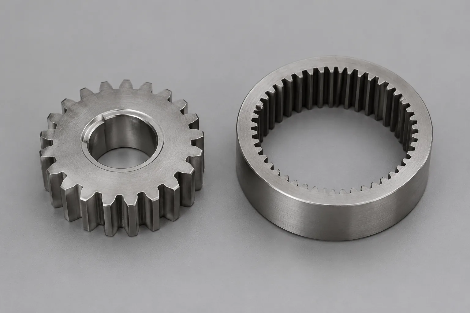
Typical matches are straightforward. Hobbing suits external spur and helical gears. Shaping suits internal gears and parts with shoulders. Broaching suits high-volume internal splines and gears. Casting suits large, low-precision gears. Powder metallurgy suits high-volume small gears. Injection molding suits plastic gears.
Total cost includes more than the cutting operation. Tooling, machining time, heat treatment, finishing, inspection, and scrap all belong in the comparison. Selection should be confirmed with a manufacturing engineer or supplier using a detailed drawing, because actual capability varies by machine, tooling, and quality system.
Common Gear Manufacturing Defects and How to Avoid Them
Common issues include tooth thickness errors, profile deviation, lead deviation, runout, heat-treatment distortion, surface cracks, burrs, and poor surface finish. Their causes are often visible in the process record: tool wear, incorrect setup, material inconsistency, heat-treatment stress, or insufficient finishing.
Prevention is mostly process control:
- Inspect and replace tooling before wear reaches the limit.
- Verify setup, workholding, and indexing before the first cut.
- Use stress relief and controlled heat-treatment fixturing where distortion is a risk.
- Leave enough stock for finishing and confirm the finishing route before heat treatment.
- Deburr and inspect edges, not just the nominal tooth dimensions.
Defect analysis should use measured inspection data and process records. A runout reading alone does not prove whether the cause is the blank, the fixture, the cutter, or the heat-treatment cycle.
Gear Manufacturing Process Comparison
The table below compares common methods at a practical level. The ratings are qualitative; actual capability varies by manufacturer, machine, tooling, and quality plan.
| Method | Typical precision | Volume fit | Tooling cost | Common materials | Typical applications |
|---|---|---|---|---|---|
| Hobbing | Moderate to high | Medium to high | Moderate | Steel, cast iron, non-ferrous | External spur and helical gears |
| Shaping | Moderate to high | Medium to high | Moderate to high | Steel, cast iron, non-ferrous | Internal gears, shoulder-adjacent gears |
| Milling | Low to moderate | Low volume, repair, prototypes | Low to moderate | Steel, cast iron, non-ferrous, plastic | Large gears, prototypes, repair work |
| Broaching | Moderate to high | High volume | High | Steel, cast iron, non-ferrous | Internal gears, splines |
| Casting | Low to moderate | Low to high | Low to high | Cast iron, steel, aluminum, bronze | Large gears, complex blanks |
| Forging | Moderate after machining | Medium to high | Moderate to high | Carbon and alloy steel | Highly loaded transmission gears |
| Cold forming and rolling | Moderate to high | High volume | Moderate to high | Steel, non-ferrous | Splines, gear-like profiles, high-volume parts |
| Powder metallurgy | Moderate | High volume | Moderate to high | Metal powder blends | Small-to-medium lower-load gears |
| Injection molding | Moderate | High volume | High | Acetal, nylon, POM, PEEK | Plastic gears with integrated features |
| Additive manufacturing | Low to moderate | Prototypes, low volume | Low | Photopolymer, nylon, metal powder | Fit checks, custom low-volume gears |
Read the table as a starting point, not a capability guarantee. Tolerance ranges and volume thresholds must be confirmed with the supplier for the specific gear.
Conclusion
How gears are made comes down to a sequence: fix the design and material, prepare a stable blank, choose a tooth-making method, heat treat only when the duty requires it, finish to the needed accuracy, and inspect what affects function. The method should follow the application, not the other way around.
Before requesting a quote, provide a drawing or a complete specification with tooth geometry, tolerances, material, heat treatment, finishing, inspection, and volume. That package lets the manufacturer choose between hobbing, shaping, milling, broaching, casting, forging, powder metallurgy, molding, or additive manufacturing on evidence rather than assumption.
FAQs
Q1: What information is needed to manufacture a custom gear?
A: A drawing or complete specification should give module or diametral pitch, number of teeth, pressure angle, helix angle, tooth profile, face width, bore, keyway, mounting features, quality grade, material, heat treatment, finishing, and inspection requirements. Without those details, the supplier can quote only a general machining route, not a controlled gear.
Q2: Is hobbing the same as gear cutting?
A: Hobbing is one gear-cutting method, not a synonym for all gear cutting. It uses a rotating hob to generate external spur or helical teeth; shaping, milling, and broaching are separate cutting methods with different part shapes and volume economics.
Q3: What is the most common gear manufacturing process?
A: Hobbing is a common route for external spur and helical gears because it is productive and accurate. The most common process for a specific part still depends on volume, material, gear type, and precision; internal gears often point to shaping or broaching, while plastic gears often point to injection molding.
Q4: Are all gears machined?
A: No. Gears can be cast, forged, formed, powder metallurgy molded, injection molded, or additively manufactured. Many of those routes still machine the teeth or critical surfaces afterward when accuracy or surface finish matters.
Q5: How are plastic gears made?
A: Plastic gears are commonly injection molded at high volume. The mold, gate location, shrinkage allowance, and material grade control tooth accuracy; acetal, nylon, POM, and PEEK are common families, but the exact grade should be selected from the material datasheet for load, temperature, and lubrication.
Q6: What is the difference between hobbing and gear shaping?
A: Hobbing uses a rotating hob and is well suited to external spur and helical gears. Gear shaping uses a reciprocating gear-shaped cutter and can reach internal gears and shoulders that a hob cannot. Shaping is generally slower and may need a special cutter.
Q7: How precise can manufactured gears be?
A: Precision depends on the process, material, heat treatment, finishing, and inspection grade. Cutting can produce commercial gears; grinding, shaving, honing, and lapping can improve accuracy and surface finish. The drawing should state the ISO, AGMA, DIN, or JIS grade and the measured features, because a general statement such as “precision gear” is not a specification.
Q8: Why are gears heat treated?
A: Heat treatment raises wear resistance, fatigue strength, and load capacity. Through hardening, carburizing, nitriding, induction hardening, and case hardening are common, but they can distort the gear, so hard finishing may be needed afterward. Plastic and some low-load gears do not need heat treatment.
Q9: How are internal gears made?
A: Internal gears are commonly shaped or broached. Shaping can generate internal teeth with a reciprocating cutter; broaching can cut internal gears and splines in high volume with expensive tooling. Hobbing is generally not the first choice for internal teeth because the hob and arbor need clearance.
Q10: Can gears be 3D printed?
A: Yes, for prototypes, fit checks, and low-volume custom parts. Printed gears usually have lower surface finish, dimensional accuracy, and fatigue performance than machined metal gears, so a highly loaded production gear needs validation before additive manufacturing is accepted.