Quick Answer
A thrust bearing is a machine element designed to support axial loads—forces that act parallel to the shaft axis. It enables smooth rotation between moving and stationary parts by using rolling elements (balls or rollers) to convert sliding friction into rolling friction. Thrust bearings are essential in automotive transmissions, marine propellers, industrial gearboxes, and aerospace actuators. Proper type selection depends on load magnitude, speed, alignment conditions, and space constraints.
Imagine a spinning fan or a car turning a corner. In both cases, there are forces trying to push the rotating shaft out of its position along its axis. Managing this axial thrust is critical for any machinery to function smoothly and reliably. This is precisely where a thrust bearing comes into play.
Whether you are a design engineer specifying components for a new project or a procurement specialist looking for reliable suppliers, understanding thrust bearings is fundamental. This comprehensive guide will walk you through everything you need to know—from basic definitions and working principles to detailed type classifications, selection criteria, and maintenance best practices. Our goal is to provide you with the authoritative knowledge needed to make informed decisions for your applications.
What Is a Thrust Bearing and How Does It Differ from a Radial Bearing?
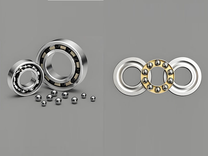
To understand a thrust bearing, it’s easiest to contrast it with its more common counterpart: the radial bearing.
Radial Bearings are designed to support loads that are perpendicular (radial) to the shaft. Think of a weight sitting on top of a rotating rod, like a conveyor belt roller.
Thrust Bearings, on the other hand, are specifically engineered to support loads that are parallel (axial) to the shaft. Imagine the force generated when a car goes around a curve, pushing the wheel hub inward, or the massive weight of a hydroelectric turbine’s runner pushing down on its support structure.
In essence, a thrust bearing is a specialized machine element that permits rotation between parts while carrying an axial load. It achieves this by providing a low-friction surface between rotating and stationary components, typically through rolling elements like balls or rollers.
How Does a Thrust Bearing Work?
The fundamental principle behind a thrust bearing is the conversion of sliding friction into the much lower rolling friction.
A typical thrust bearing consists of three main parts: two washers (or races) and a set of rolling elements (balls or rollers) held in a cage or separator.
- The Stationary Race: One washer is fixed to the machine housing or a stationary part.
- The Rotating Race: The other washer is attached to the rotating shaft.
- Rolling Elements: As the shaft rotates, the rotating race turns, and the rolling elements roll between the two races. This rolling action supports the axial load while allowing for smooth, low-friction rotation.
A thin film of lubricant (oil or grease) is crucial to separate the rolling elements from the races, preventing metal-to-metal contact, reducing wear, and dissipating heat.
Main Types of Thrust Bearings and Their Applications
Thrust bearings come in various designs, each optimized for specific load, speed, and alignment conditions. Selecting the correct type is paramount for performance and longevity.
Thrust Ball Bearings
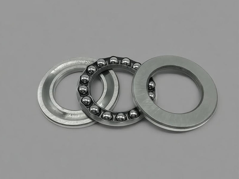
These are the most common type, using ball bearings as the rolling elements. They are suitable for moderate axial loads and high-speed operations but have limited load capacity compared to roller types.
- Single-Direction Thrust Ball Bearings: Designed to accommodate axial load in one direction only. They consist of a shaft ring, a housing ring, and a ball and cage assembly. Common in crane hooks, and machine tool spindles.
- Double-Direction Thrust Ball Bearings: Capable of supporting axial loads in both directions. They feature three races (shaft, housing, and a middle ring) and two ball and cage assemblies. Often used in applications like vertical pumps and steering knuckles in vehicles.
Thrust Roller Bearings
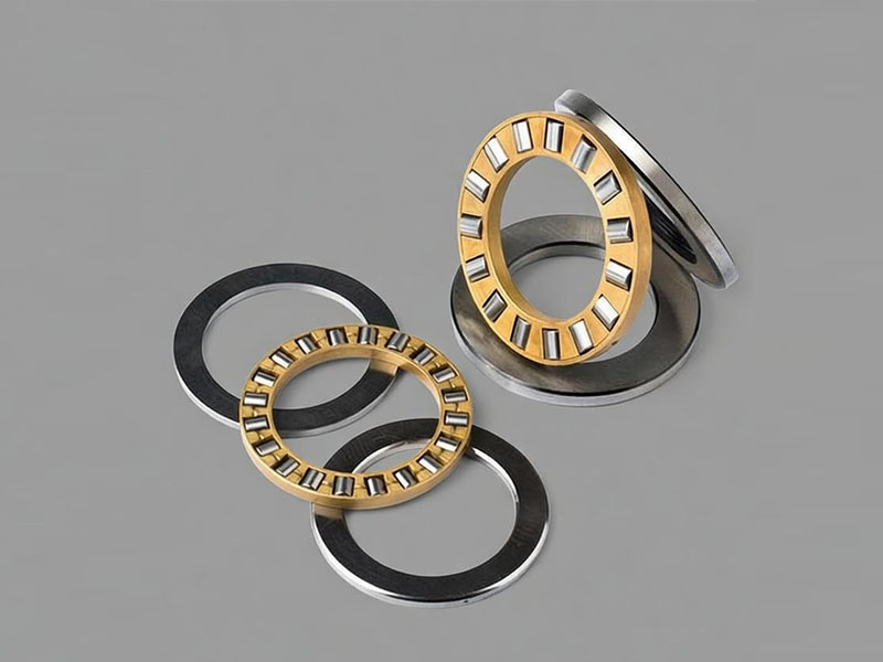
For applications demanding higher load capacity, thrust roller bearings are the answer. They use cylindrical, tapered, or spherical rollers to provide a larger contact area.
- Cylindrical Thrust Roller Bearings: Offer very high rigidity and are ideal for heavy axial loads and impact loads. Their line contact provides superior load-carrying capacity. Commonly found in heavy-duty gearboxes and marine gear drives.
- Tapered Thrust Roller Bearings: Designed to handle loads (both axial and radial) simultaneously. This makes them extremely versatile. A prime example is their use in automotive wheel hubs, where they must bear the vehicle’s weight (radial) and cornering forces (axial).
- Spherical Thrust Roller Bearings: A highly sophisticated bearing type featuring spherical rollers that run in a similarly spherical raceway. This design provides a self-aligning feature, meaning the bearing can compensate for shaft misalignment or deflection caused by heavy loads. They are perfect for extremely heavy, low-speed applications with potential misalignment, such as large hydroelectric generators, mining equipment, and offshore drilling rigs.
- Thrust Needle Roller Bearings: Utilizing very thin cylindrical rollers (needles), these bearings have a minimal cross-sectional height, making them excellent for applications with tight axial space constraints. They are widely used in automotive automatic transmissions and hydraulic pumps.
Angular Contact Thrust Ball Bearings
While technically a ball bearing, this type deserves its own mention. It is designed with raceways that are displaced relative to the bearing axis, allowing it to support combined radial and axial loads at high speeds. They are often used in pairs (back-to-back, face-to-face, or in tandem) in precision applications like machine tool spindles and high-speed centrifuges.
How to Select the Right Thrust Bearing for Your Application
Choosing a thrust bearing isn’t just about finding one that fits. It’s about matching the bearing’s capabilities to the exact demands of your machinery. Here are the critical factors to evaluate:
- Load Analysis: Determine the magnitude and direction (single or double) of the axial load. Is it constant or does it involve shock or vibration? For pure, heavy axial loads, a roller bearing is preferable; for lighter, high-speed loads, a ball bearing may suffice.
- Speed Requirements: Every bearing type has a maximum speed rating. High-speed applications often favor ball bearings for their lower friction, while some specialized roller bearings are also designed for high speeds with advanced lubrication systems.
- Alignment and Space Constraints: Consider if the shaft is prone to bending or if there are potential misalignments in the housing. If so, a spherical thrust roller bearing’s self-aligning capability is invaluable. Also, if axial space is limited, a thrust needle roller bearing is the optimal choice.
- Lubrication and Maintenance: The choice between grease and oil lubrication depends on speed, temperature, and load. Consider the maintenance access and desired service intervals. Bearings with better seals or those designed for relubrication can reduce maintenance burdens.
Thrust Bearing Selection Guide – Type Comparison
Use this comparison to quickly narrow down your options based on your application’s primary requirements. Each type is designed for a specific combination of load, speed, and alignment conditions.
| Selection Factor | Thrust Ball Bearings | Thrust Roller Bearings | Spherical Thrust Roller Bearings |
|---|---|---|---|
| Load capacity | Moderate | High to very high | Very high |
| Speed capability | High | Moderate to high (depending on design) | Low to moderate |
| Misalignment tolerance | Limited | Limited (except spherical type) | Excellent (self-aligning) |
| Typical load range | Light to moderate (< 30 kN) | Heavy (30–500 kN) | Extremely heavy (> 200 kN) |
| Speed range | Up to 5,000–10,000 rpm (depends on size) | Typically 1,000–5,000 rpm | Typically < 1,000 rpm |
| Recommended for | High-speed, lighter axial loads | Heavy loads, impact conditions | Heavy loads with misalignment risk |
Best Practices for Installation and Maintenance
Even the highest quality bearing will fail prematurely if not installed and maintained correctly. Following these best practices ensures maximum service life and reliability.
Proper Installation
- Cleanliness: Keep the bearing and its surroundings scrupulously clean. Even microscopic contaminants can cause damage.
- Careful Handling: Never apply force directly through the rolling elements. Use a press or appropriate tools to apply force evenly on the race ring being mounted.
- Correct Alignment: Ensure the shaft shoulder and housing bore are perpendicular to the shaft axis. Misalignment is a leading cause of premature failure.
Effective Maintenance
- Regular Lubrication: Adhere to the manufacturer’s recommendations for lubricant type, quantity, and re-lubrication intervals. Proper lubrication is the lifeblood of any bearing.
- Condition Monitoring: Listen for unusual noises (grinding, rattling) and monitor operating temperature. A sudden increase in either is often the first sign of a problem.
- Scheduled Inspections: During routine maintenance, inspect bearings for signs of wear, corrosion, or discoloration (indicating overheating).
Installation and Maintenance Quick Reference Checklist
Before installation, prepare the workspace and verify all tools are ready. Inspect the bearing for shipping damage and confirm dimensions against specifications. Check the shaft and housing for burrs and proper tolerances. During mounting, apply force only to the race ring being mounted—never through rolling elements. For interference fits, heat the housing uniformly to 80–90°C.
After mounting, verify alignment using a dial indicator; acceptable total indicated runout is typically 0.01–0.05 mm for precision applications. Rotate the shaft by hand to confirm smooth motion with no binding. Apply lubricant—fill 30–50% of internal free space for grease lubrication. Run the machine at 25% of normal speed for 15–30 minutes, gradually increasing to full speed while monitoring temperature.
For ongoing maintenance, establish daily checks (temperature, noise, leaks), weekly inspections (seals, bolt torque), and scheduled overhauls per operating hours. Re-greasing frequency depends on temperature, contamination, moisture, vibration, and runtime—higher values in any factor shorten the interval.
For detailed step-by-step installation and maintenance procedures, refer to the full Thrust Bearing Installation and Maintenance Guide.
Common Failure Modes and Root Cause Analysis
Understanding why bearings fail is the first step in preventing it. Here’s a quick guide to common failure modes and their root causes:
| Failure Mode | Possible Root Causes | Prevention |
|---|---|---|
| Overheating | Insufficient lubrication, excessive load, high speed, or tight fits | Verify lubrication plan, check load calculations, ensure correct fitting |
| Abnormal Noise/Vibration | Contamination, misalignment, insufficient lubrication, brinelling (damage from shock) | Improve sealing, ensure precise alignment, handle with care during installation |
| Spalling (Flaking) | Fatigue due to normal end of life, excessive preload, or misalignment | This is often the natural failure mode. For premature cases, re-evaluate load and alignment |
| Wear | Contaminant ingress, inadequate lubrication | Upgrade seals, ensure clean lubricant supply |
| Corrosion | Moisture or corrosive agents entering the bearing | Improve sealing, use corrosion-resistant lubricants, consider coated bearings |
Quick Failure Diagnosis Guide
When a bearing shows signs of trouble, use this diagnostic sequence to identify the likely failure mode before disassembly.
First Check: Is there a sudden temperature rise above normal baseline (sustained above 100°C for standard grease)?
- Yes → Likely overheating. Check lubricant level and condition immediately. Verify load and speed are within bearing limits.
- No → Proceed to next check.
Second Check: Is there unusual noise—grinding, rattling, or rhythmic knocking?
- Grinding → Likely contamination or abrasive wear. Check seals and lubricant cleanliness.
- Rhythmic knocking → Likely brinelling or spalling. Schedule inspection for raceway damage.
- No unusual noise → Proceed to next check.
Third Check: Is there visible rust, pitting, or discoloration on the bearing exterior or shaft?
- Rust or pitting → Likely corrosion. Check seals and operating environment for moisture.
- Blue/brown discoloration → Likely overheating. Verify lubricant condition and load.
- No visible signs → Perform scheduled inspection to catch issues early.
If any of the above signs are present, dismantle the bearing, clean thoroughly, and inspect raceways and rolling elements. For in-depth failure diagnosis and troubleshooting—including detailed visual inspection steps, root cause analysis, and replacement vs. repair decisions—refer to the full Thrust Bearing Failure Analysis guide.
Conclusion
Thrust bearings are fundamental components that manage axial forces across countless industries—from the simple thrust ball bearing in a hand drill to the massive spherical roller thrust bearing supporting a multi-ton turbine. Understanding the distinctions between types, selecting based on load-speed-alignment conditions, and following proper installation and maintenance practices are essential for achieving reliable, long-lasting operation.
When selecting a thrust bearing, start by defining your load requirements: magnitude, direction, and whether it involves shock or vibration. Then evaluate speed demands, alignment constraints, and available space. Use the type comparison table as a decision tool to match your application with the right bearing design.
For those seeking deeper technical guidance, detailed step-by-step installation procedures and maintenance schedules are covered in the Thrust Bearing Installation and Maintenance Guide. For failure diagnosis and troubleshooting—including visual inspection steps and root cause analysis—refer to the Thrust Bearing Failure Analysis guide.
Frequently Asked Questions (FAQ)
Q1: What is the main purpose of a thrust bearing?
A: A thrust bearing is designed to support axial loads—forces that act parallel to the shaft axis. Unlike radial bearings that handle perpendicular forces, thrust bearings prevent axial movement of rotating components while allowing smooth rotation. Typical applications include automotive transmissions, steering columns, marine propeller shafts, and heavy-duty industrial gearboxes.
Q2: How does a thrust bearing differ from a radial bearing in terms of load direction?
A: Radial bearings support loads perpendicular to the shaft axis (e.g., the weight of a wheel on an axle). Thrust bearings support loads parallel to the shaft axis (e.g., the forward/backward push from a propeller or a car’s clutch pressure plate). Some bearings—such as angular contact ball bearings—can manage combined loads, but pure thrust bearings are optimized for axial forces only.
Q3: What are the common types of thrust bearings?
A: The main types include thrust ball bearings (single-direction and double-direction), thrust roller bearings (cylindrical, tapered, spherical, and needle roller types), and angular contact thrust ball bearings. Each type is optimized for different combinations of load magnitude, speed, and alignment conditions.
Q4: How do I choose the right thrust bearing type for my application?
A: Consider four key factors: load magnitude and direction (single or double), operating speed, alignment and space constraints, and lubrication/maintenance requirements. Use the type comparison table in this guide as a starting point. For heavy axial loads, choose roller types; for high-speed applications, ball types are preferred; for misalignment conditions, spherical roller thrust bearings are the solution.
Q5: What is a thrust bearing also known as?
A: Thrust bearings are commonly referred to as axial bearings (because they carry axial loads). Depending on the rolling element, they may also be called thrust ball bearings, thrust roller bearings, spherical roller thrust bearings, or tapered roller thrust bearings. In some industries, they are simply named “axial load bearings.”
Q6: What are the typical applications of a thrust bearing?
A: Thrust bearings are used wherever axial forces must be controlled. Common applications include automotive (automatic transmissions, clutch release mechanisms, steering columns, wheel hubs), marine (propeller shaft bearings absorbing water thrust), industrial (crane swivels, heavy-duty gearboxes, extruders, vertical pumps), and aerospace (helicopter rotor hubs, landing gear actuators).
Q7: When should I choose a spherical roller thrust bearing over other thrust bearing types?
A: Select a spherical roller thrust bearing when you need to accommodate high axial loads (often combined with moderate radial loads), misalignment (their spherical raceway allows angular errors typically up to 1.5°–2° without stress concentration), or shock/vibration (the robust roller design handles dynamic loads better than ball thrust bearings). Typical uses include wind turbine main shafts, hydroelectric turbines, and heavy crane hooks.
Q8: What materials are commonly used for thrust bearings in heavy-load applications?
A: For heavy-duty thrust bearings, manufacturers use bearing steel (GCr15 / AISI 52100) for high hardness and wear resistance; case-hardened steel for shock-prone applications; bronze or PTFE composites for high-speed, low-load thrust washers; and ceramic balls (Si3N4) in hybrid thrust bearings for high speed and electric motor insulation.
Q9: Can a thrust bearing also support radial loads?
A: Pure thrust bearings (e.g., flat thrust ball bearings) are not designed for radial loads. Applying radial load to a pure thrust bearing will cause rapid wear and failure. However, angular contact thrust bearings (including tapered roller thrust bearings and spherical roller thrust bearings) can support combined axial and radial loads. Always check the manufacturer’s load rating before selection.