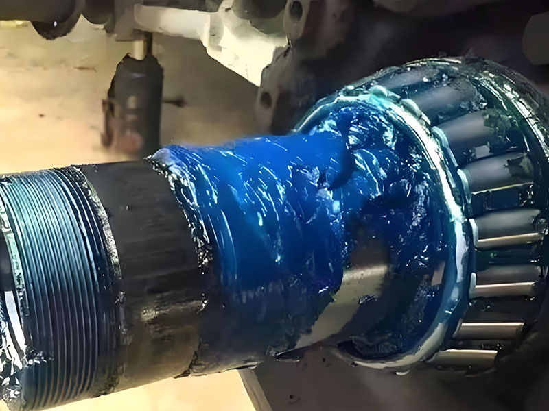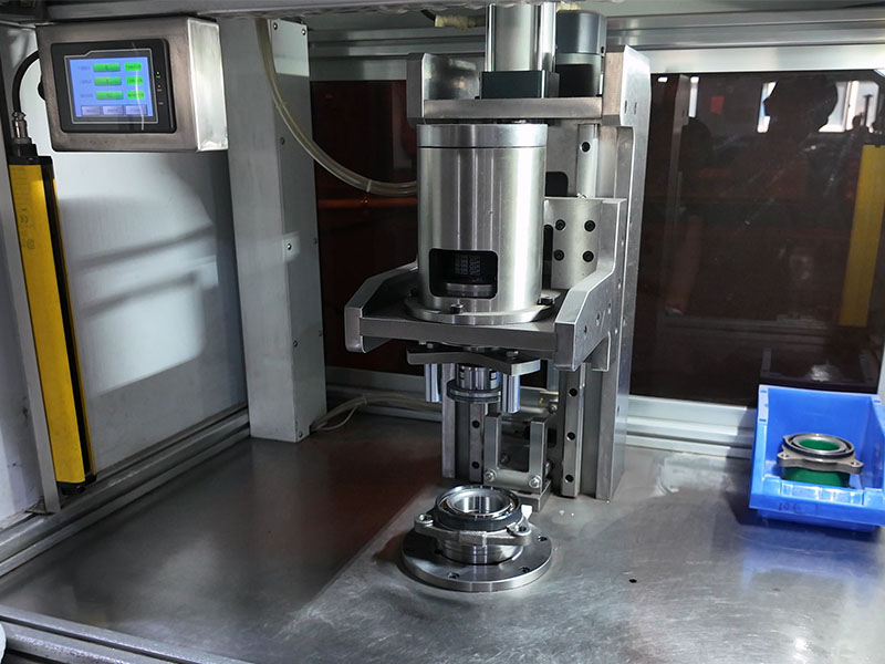
Quick Answer: Radial load is the force perpendicular to the motor shaft axis. It is a primary input to motor bearing sizing because it drives equivalent dynamic load, rating life, static checks, clearance selection and minimum-load checks. Size a motor bearing by combining every radial load source with axial load, load application point, speed, target life and the locating or non-locating bearing function.
Motor bearing sizing often starts with a catalogue number when the real question is load. A bearing dimension cannot be judged until the radial load, axial load, load point, speed and required life are known. Missing one of those inputs can make a bearing look adequate on paper while its calculated life, clearance or minimum-load margin fails in service.
Radial load is a key factor in motor bearing sizing because it is not a single catalogue value. It is a load case built from rotor weight, driven equipment, transmission tension, unbalance, inertia and the geometry of the shaft extension. The sections below show how those inputs connect to bearing type, life, static rating, clearance and minimum load.
Radial Load in Motor Bearings: Definition and Role
Radial load acts perpendicular to the motor shaft axis. Axial load, also called thrust load, acts along the same axis. The distinction matters because a bearing that is strong in one direction may be weak or unsuitable in the other.
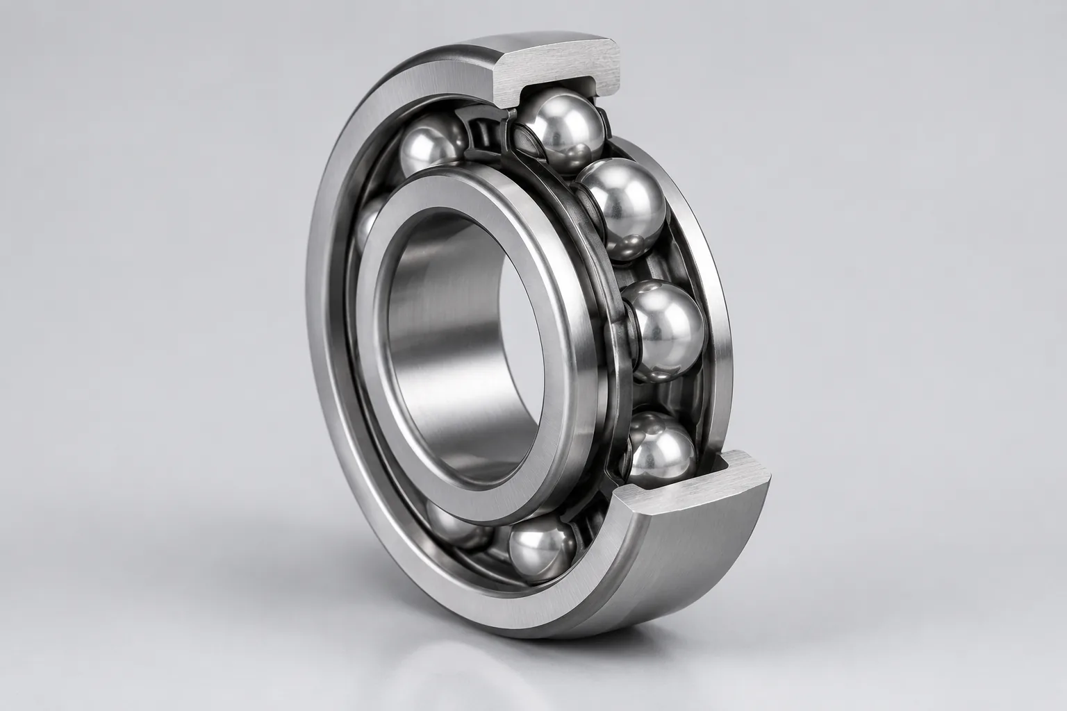
Rolling bearings are grouped by their main load direction. Radial bearings are intended primarily for loads perpendicular to the shaft, while thrust bearings are intended primarily for loads along the shaft. A motor bearing system usually has to do both jobs at once: support the rotor radially and hold its axial position relative to the stator.
A common arrangement uses one locating bearing and one non-locating bearing. The locating bearing controls axial position. The non-locating bearing must allow the shaft to expand with temperature so that thermal growth does not create an unintended axial load.
Where Radial Load Originates in Electric Motors
Rotor weight is only one source of radial load. A complete load case includes every mass, tension and dynamic force that reaches the bearing through the shaft.
- The weight of the shaft, rotor, flywheel, pulley, gear and other rotor-mounted components.
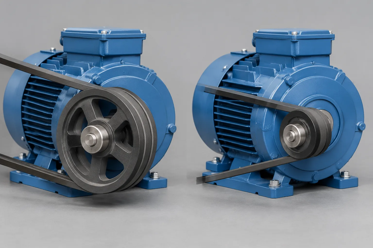
- Belt or chain tension and the overhung load from a pulley or sprocket.
- Gear-generated tangential and separating forces, plus axial components where the gear type produces them.
- Inertia loads from acceleration and deceleration.
- Centrifugal force from rotating unbalance.
Rotor weight alone is not a sizing load case. A small motor with a tight belt or a large overhung pulley can place a higher radial load on the bearing than a heavier rotor with no external drive.
Radial vs Axial Load: Combined-Load Consequences
Do not size a motor bearing on radial load alone when axial load exists. Deep groove ball bearings can carry combined radial and axial loads. Cylindrical roller bearings are primarily radial load bearings, so their axial capability and locating function need separate checking.
For combined loading, the general equivalent dynamic bearing load is:
P = XFr + YFa
Here Fr is the radial load, Fa is the axial load, and X and Y depend on bearing type, contact angle and the load ratio. For a cylindrical roller bearing under pure radial load, the equivalent dynamic load reduces to P = Fr.
P = Fr is valid only when axial load is absent for the bearing and operating case being checked. It is not a shortcut for a combined-load application. Ignoring axial load can change the required bearing type, the locating arrangement and the calculated life.
Load Path from Shaft Extension to Bearing
A force applied outside the bearing span is a radial overhung load. The bearing sees both the force and the bending moment created by its distance from the bearing. Two drives with the same force can produce different bearing loads when the load application point changes.
A load placed farther from the bearing increases the bending moment and normally lowers the permissible radial force. Motor-makers express this with a position-dependent limit. One common form is:
FR = Fx0 – (X/E)(Fx0 – Fxmax)
In this formula, X is the load application point and E is the standard shaft extension length. Here X is a position, not the dynamic load coefficient used in P = XFr + YFa. FR is the permissible radial force at that point. The formula uses the published limit values Fx0 and Fxmax from the motor-maker table.
Use motor-maker permissible radial force tables only inside their stated boundary conditions. A typical table may assume zero axial load, 25°C ambient temperature, normal operating conditions, IM B3 foot mounting and a side-acting load, with separate values for 20,000 hours and 40,000 hours. If the actual installation has axial load, a different mounting, a different ambient or another load direction, the table value is not a direct answer.
Where the motor standard applies, check the radial overhung load provisions. ANSI/NEMA MG 1-2016 section 14.42 covers V-belt pulley applications for AC motors with anti-friction bearings, and section 14.42.2 addresses radial overhung load limitations.
Belt and Pulley Radial Load Calculation
Belt-driven radial load can be estimated from transmitted power, speed, pulley diameter and belt pretension. A common preliminary approximation is:
FQ = c x Fu
Fu = 2 x 10^7 x P/(n x D)
Here FQ is the total cantilever radial force in N, Fu is the tangential force term, P is transmitted power in kW, n is speed in r/min, D is pulley diameter in mm, and c is the belt pretension factor. For ordinary V-belts, c is approximately 2 to 2.5. In this formula, P is power, not the equivalent dynamic bearing load used later.
When the permissible radial force is already defined, a minimum pulley diameter form can be used:
D = 1.9 x 10^7 x K x P/(n x FR)
Here D is pulley diameter in mm, K is the belt tension factor, FR is the permissible radial force in N, and P and n keep the same units. For V-belts, K is commonly 2.5 in this form.
At fixed power and speed, reducing pulley diameter increases the radial load on the motor bearing because diameter appears in the denominator. Belt formulas are approximate sizing aids. Final design should use the actual belt tension and the belt manufacturer’s data, because different belt types and tensioning methods can require different pretension factors.
Equivalent Dynamic Load and Rating Life
After the radial and axial loads are combined into equivalent dynamic load P, compare P with the bearing’s basic dynamic load rating C. The basic rating life in revolutions is:
L10 = (C/P)^p
For life in hours:
L10h = [10^6/(60n)] x (C/P)^p
Here n is speed in r/min. Use p = 3 for ball bearings and p = 10/3 for roller bearings. L10 corresponds to 90% reliability for a group of identical bearings under identical conditions. It is a standardized calculation, not a guarantee for every individual bearing.
Small radial load increases can sharply reduce calculated life because load enters the equation exponentially. If load doubles while C, speed and other conditions stay unchanged, a ball bearing’s calculated life falls to 1/2^3 = 1/8. A roller bearing’s calculated life falls to about 1/2^(10/3) = 1/10.1.
ISO 281:2007 defines methods for basic dynamic load ratings, basic rating life and modified rating life. It was published in February 2007 and confirmed in 2021. Modified life can account for reliability, lubrication, contamination and the fatigue load limit. Those modifiers still require valid operating inputs; they do not replace the load case.
Static Load Rating and ISO 76 Checks
A dynamic life calculation is not the only check. Heavy loads, low speed, shock or stationary conditions can make static rating the controlling check. Compare the static equivalent load with the basic static load rating C0 and use static safety factor guidance for the application.
ISO 76:2006 provides methods for basic static load ratings and static equivalent loads and gives static safety factor guidance for heavily loaded applications. It was published in May 2006, and the amendment ISO 76:2006/Amd 1:2017 exists. Do not use C and C0 interchangeably: C belongs to dynamic rating life, while C0 belongs to static load capacity.
Standard static calculation assumes a normal load distribution. Misalignment, preload or excessive clearance can produce an abnormal load distribution, and the standard notes that the result may not be satisfactory. In that case, consult the bearing manufacturer for static equivalent load evaluation rather than forcing the standard formula onto the case.
Bearing Type Selection for Radial Capacity
Radial capacity is one selection input, not the whole decision. The locating and non-locating functions must be assigned before the final bearing type is chosen.
| Bearing type | Main load direction | Radial capacity | Application notes |
|---|---|---|---|
| Single-row deep groove ball bearing | Combined radial and axial | Moderate | Suits high speed and is widely used for versatility and cost effectiveness |
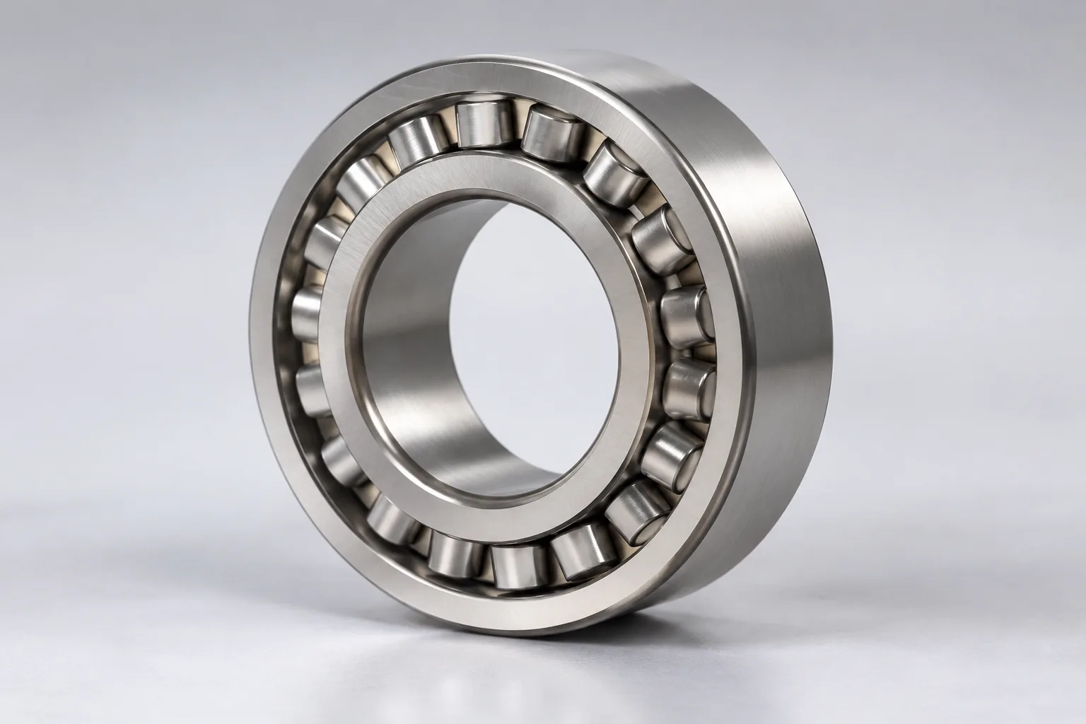
| Cylindrical roller bearing | Mainly radial | Generally higher than a same-size ball bearing | Line contact; generally lower high-speed capability; check minimum radial load |
Single-row deep groove ball bearings can carry radial and axial forces, suit high-speed operation and are common because of their versatility and cost effectiveness. Cylindrical roller bearings use line contact, mainly carry radial load and generally offer higher radial capacity than same-size ball bearings, but their high-speed capability is generally lower.
In most medium and large motors, the locating end commonly uses a deep groove ball bearing. The non-locating end may use a deep groove ball bearing, an N or NU cylindrical roller bearing, or a toroidal roller bearing. Small motors with short shafts often use two deep groove ball bearings in a cross-located arrangement.
The non-locating bearing must allow thermal shaft elongation so that growth does not create extra axial load. N and NU cylindrical roller bearings allow axial displacement within the bearing while mainly carrying radial load. A bearing that is radially strong but axially trapped in the wrong position can still fail the application.
Permissible Radial Force and Life Target
Permissible radial force depends on bearing type, motor frame, speed, shaft extension, load application point and target life. It is an application-specific limit, not a universal bearing rating. A longer target life reduces the permissible radial force for the same motor and bearing because the bearing must carry the same load for more hours.
One published motor-maker example for a 160 frame, 3,000 r/min and 110 mm shaft extension shows the effect. At 20,000 hours, the permissible radial force at the shaft extension is 3,540 N for a ball bearing and 7,100 N for a roller bearing. At 40,000 hours, the same positions fall to 2,955 N for the ball bearing and 6,140 N for the roller bearing.
Those values apply only within the table boundary conditions, including zero axial load, 25°C ambient, normal operating conditions, IM B3 mounting and side-acting load. Compare ball and roller options against the actual required life and load point. A higher radial capacity does not help if the bearing does not fit the locating function, speed or minimum-load requirement.
Internal Clearance, Fit, and Thermal Effects
Radial internal clearance affects bearing operation and must be considered together with radial load. Common radial clearance grades include C1, C2, CN, C3, C4 and C5. Motor deep groove ball bearings may use CM clearance, and motor cylindrical roller bearings may use CT or CM clearance.
Interference fits and operating temperature rise reduce the actual operating clearance. A bearing selected with a nominal clearance can run tighter after the inner ring is pressed onto the shaft and the motor reaches operating temperature. Do not select clearance from load rating alone. The fit, housing material, temperature difference and shaft expansion all belong in the same check.
Minimum Radial Load in Roller Bearings
A higher radial capacity does not mean the bearing is always the better choice. Cylindrical roller bearings need sufficient minimum radial load, especially at high speed. If the radial load is too low, roller inertia and lubricant friction can cause sliding instead of proper rolling, which damages the raceway and roller surfaces.
Use bearing-specific minimum load data rather than a generic rule. For example, one published table for NU/N/NJ 310 EC gives minimum radial loads of about 142 lb at 900 rpm, 153 lb at 1,800 rpm and 176 lb at 3,600 rpm. The value rises with speed. Check the light-load and high-speed operating points whenever a larger roller bearing is selected for radial capacity.
What ISO 281 Does Not Cover: Electrical Erosion and Other Limits
ISO 281 rating life does not cover wear, corrosion or electrical erosion. A passing radial load life calculation therefore does not prove that the bearing is suitable for a variable-frequency drive application. Shaft current, electrical erosion and insulated bearing needs must be evaluated separately.
Modified life methods can include reliability, lubrication, contamination and the fatigue load limit, but they do not cover every motor-specific failure mode. Keep mechanical load sizing separate from electrical and lubrication failure mechanisms. A bearing can meet its calculated radial load life and still fail from electrical pitting, contamination or inadequate lubrication.
Motor Bearing Sizing Workflow
Use a repeatable sequence so that no load source or limit is missed:
- Define all radial and axial load components and their directions.
- Define each load application point and overhung moment arm.
- Assign locating and non-locating bearing functions.
- Calculate equivalent dynamic load P and the required C for the target L10h.
- Perform the static load check with C0 and static equivalent load where relevant.
- Verify internal clearance, fit, operating temperature and minimum radial load.
- Check motor-maker permissible radial force tables or bearing calculation software within their stated conditions.
- Document assumptions, load cases and life target for review.
Repeat the workflow for the worst radial load case and for combined radial-axial load cases. A bearing selected on a light running load can be undersized for start-up, belt tension or an abnormal unbalance case.
Common Mistakes in Radial Load Sizing
- Using rotor weight as the only radial load.
- Ignoring belt or chain pretension and pulley overhung load.
- Applying a permissible radial force table without checking its boundary conditions.
- Using C and C0 interchangeably.
- Selecting a cylindrical roller bearing for high radial capacity without checking minimum load and speed limits.
- Ignoring axial load in combined-load applications.
- Ignoring the load application point along the shaft extension.
- Assuming ISO 281 life calculation covers electrical erosion.
Some of these shortcuts may be acceptable as preliminary estimates before detailed load data is available. They are not valid for final sizing or for a purchasing decision on a motor bearing.
Conclusion
Radial load is a key factor in motor bearing sizing because it is a load case, not a catalogue lookup. Build the case from rotor weight, driven components, belt or chain tension, gear forces, inertia and unbalance. Keep axial load, load application point, speed and target life attached to the calculation. Then check dynamic rating life, static rating, bearing type, clearance, fit, minimum radial load and electrical limits as separate decision points.
The safe next step is to list every operating case, identify the worst radial and combined load, and compare the result with the motor-maker permissible radial force data and the selected bearing’s C, C0 and minimum load requirements. If the application uses a variable-frequency drive, evaluate shaft current and electrical erosion separately from the ISO 281 life result.
FAQs
These answers clarify the definitions, calculation inputs, standards and bearing-type trade-offs behind radial load sizing.
Q1: What is radial load in a motor bearing?
A: Radial load is the force acting perpendicular to the motor shaft axis. It is distinct from axial or thrust load, which acts along the shaft axis. A motor bearing must support the radial load and, depending on its locating function, may also carry axial load.
Q2: Does radial load include only rotor weight?
A: No. Rotor weight is only one source. A complete radial load case also includes pulley or gear loads, belt or chain tension, unbalance, inertia from acceleration and deceleration, and other overhung loads.
Q3: How is radial load calculated for a belt-driven motor?
A: Use transmitted power, speed, pulley diameter and belt pretension factor. A common approximation is FQ = c x Fu with Fu = 2 x 10^7 x P/(n x D). For ordinary V-belts, c is about 2 to 2.5. Final design should use actual belt tension and belt manufacturer data.
Q4: Why does doubling radial load reduce bearing life so much?
A: Life is proportional to (C/P)^p. With other conditions unchanged, doubling P reduces ball bearing life to 1/8 and roller bearing life to about 1/10.1. The exponent makes load control one of the strongest levers in motor bearing sizing.
Q5: Can a cylindrical roller bearing replace a deep groove ball bearing?
A: It may be suitable when higher radial capacity is needed, but check axial load capability, speed limits, minimum radial load, clearance and the locating or non-locating function before replacement. A roller bearing is mainly a radial load bearing, so it is not a direct substitute where axial location depends on the bearing.
Q6: Which standards apply to motor bearing sizing?
A: ISO 281 covers dynamic load ratings and rating life, ISO 76 covers static load ratings, and ANSI/NEMA MG 1 includes motor provisions related to radial overhung load limitations for V-belt applications. Use the edition and scope that apply to the motor and market.
Q7: Does ISO 281 cover electrical erosion?
A: No. ISO 281 rating life does not cover wear, corrosion or electrical erosion. VFD motor applications need separate evaluation of shaft current, electrical erosion and insulated bearing requirements.
Q8: How does the life target change permissible radial force?
A: A longer required life lowers the permissible radial force for the same motor and bearing. Use application-specific permissible radial force tables or bearing calculations for the selected life target, and keep the table boundary conditions attached to the value.