Quick Answer: Radial play is the total radial movement of one bearing ring relative to the other, axial play is the same movement measured along the bearing axis, and contact angle is the angle between the rolling-element load line and a plane perpendicular to that axis. The three are linked through bearing geometry, so axial play cannot be converted from radial play with one universal ratio. Conversion depends on bearing type, groove or raceway geometry, fits, and operating temperature.
Radial play and axial play describe the same bearing geometry from two directions, and contact angle decides how the two relate. A technician setting a tapered roller pair and a buyer selecting an angular contact bearing for a spindle both work with the same three ideas: how far the rings can move, how the load line is inclined, and which value changes when the other is adjusted. Get the relationship wrong and a correctly assembled bearing can still run with the wrong operating clearance.
What Radial Play and Axial Play Mean
Radial internal clearance, often shortened to radial play, is the total distance one bearing ring can shift radially relative to the other. It is measured from one extreme to the opposite extreme with the other ring held fixed. Axial internal clearance, also known as axial play or end play, is the matching displacement measured parallel to the bearing axis.
Both values are defined for an unmounted bearing with no external load, and both are read under a specified measuring load. The condition matters: a measuring load produces elastic deformation at the contacts, so a measured value and a purely geometrical value are not the same quantity.
Internal clearance is not a cosmetic tolerance. It affects fatigue life, vibration, noise, and heat generation, which is why clearance grades are specified rather than left to assembly feel.
In bearing literature, play almost always means the internal clearance between the rings and the rolling elements. It does not mean a loose fit on the shaft or in the housing, and it is not the free looseness a worn bearing develops in service.
What Contact Angle Means
Contact angle, written α, is the angle between the load line joining the rolling element and raceway contact points and a plane perpendicular to the bearing axis, measured in the loaded condition. It describes how load is directed through the rolling element and the two races: a small angle sends most of the load radially, a large angle sends a bigger share axially.
Common classification uses the contact angle to separate bearing families. Angles from 0° to 45° correspond to radial bearings that primarily carry radial load, and angles above 45° up to 90° correspond to thrust bearings that primarily carry axial load. The 45° boundary is a convention, not a rule that a 40° bearing carries no axial load; angular contact bearings near that range are often chosen for combined loading.
Why Axial Play, Radial Play, and Contact Angle Are Linked
Because the rolling element sits between two inclined raceways, moving a ring axially also moves it radially. Change the axial play and the radial play changes with it, and the exchange rate is set by the rolling-element and raceway geometry.
No single axial-to-radial ratio applies to all bearings. A tapered roller bearing, a deep groove ball bearing, and a thrust bearing convert displacement in different ways, and even inside one family the ratio shifts with contact angle and groove geometry. The relationships below are bearing-type-specific and must not be mixed.
Tapered Roller Bearings: Δa = Δr cot α
For tapered roller bearings, the geometric relationship is Δa = Δr cot α, also written as approximately (1.5/e) Δr, where Δa is axial clearance, Δr is radial clearance, α is the contact angle, and e is the bearing calculation factor. Because cot α falls as the angle grows, a smaller contact angle produces greater axial play for the same radial play, and a larger contact angle produces less.
| Contact angle α | Δa/Δr from cot α |
|---|---|
| 15° | 3.73 |
| 25° | 2.14 |
| 30° | 1.73 |
| 40° | 1.19 |
These ratios come from cot α for an idealized tapered roller bearing geometry. They are a guide to the relationship, not a measured guarantee: real bearings add elastic deformation, misalignment, and mounting effects, and e must match the calculation basis used for the specific bearing.
Deep Groove Ball Bearings: Δa/Δr = cot(α/2)
For a single-row deep groove ball bearing the same geometry is written with the groove radii: Δr = 2(1 – cos α)(re + ri – Dw) and Δa = 2 sin α(re + ri – Dw), where re is the outer-ring groove radius, ri is the inner-ring groove radius, and Dw is the ball diameter. Dividing one expression by the other gives Δa/Δr = cot(α/2).
The half-angle in that result is the important difference. A deep groove ball bearing does not follow the cot α relationship of a tapered roller bearing, and neither expression converts angular contact, thrust, or cylindrical roller play. Applying one family’s ratio to another is one of the most common causes of a wrong clearance target.
How Contact Angle Affects Bearing Behavior
Raising the contact angle generally raises axial load capacity and axial stiffness, because a larger share of the load path runs along the axis. Smaller contact angles are commonly selected for higher speed and greater radial-load capability, because the ball runs on a more radial path with lower spin at the contacts.
Common angular contact ball bearing angles are 15°, 25°, 30°, and 40°. In spindle bearing ranges, 15° (suffix C), 17° (suffix C, M series), and 25° (suffix E) versions appear, with the 15° design biased toward high radial load and high speed and the 25° design better suited to combined radial and axial load. In common catalog designation systems for standard single-row angular contact ball bearings, suffix B denotes a 40° contact angle and suffix AC a 25° contact angle.
For a sense of scale, a 15° super-precision angular contact ball bearing with a 15 mm bore, 28 mm outside diameter, and 7 mm width can be rated at 3.19 kN dynamic load with oil-air lubrication up to 140,000 r/min. Those figures belong to one bearing and one lubrication method; they are not a general promise for 15° bearings.
Single-row angular contact ball bearings carry significant axial load in one direction only. Where both directions must be taken, face-to-face or back-to-back pairs, or double-row designs, are used, and the pair is adjusted as a set.
Clearance Grades and Relevant Standards
ISO 5753-1:2009, Rolling bearings – Internal clearance – Part 1: Radial internal clearance for radial bearings, sets radial internal clearance values for several radial bearing types, including radial groove ball bearings, self-aligning ball bearings, cylindrical roller bearings, some needle roller bearings, and spherical roller bearings. It was published in October 2009 and confirmed in a 2021 review. It defines radial clearance values for those types, not axial clearance for every bearing.
The common clearance progression runs from C1 as the tightest through C2, CN, C3, C4, and C5 as the loosest, with CN as normal clearance. ISO clearance groups are commonly mapped onto those catalog designations as Group 2 = C2, Group N = CN, Group 3 = C3, Group 4 = C4, and Group 5 = C5.
SAE ARP5483/3B, Rolling Element Bearing Axial and Radial Internal Clearance, covers measurement procedures for both axial and radial internal clearance of rolling element bearings in aircraft control systems. It was first issued on 17 March 2003, revised in 2009, and confirmed on 10 June 2026. Note what such documents do: they define values and measuring procedures, not a universal axial-to-radial conversion ratio.
Measurement, Fits, and Operating Clearance
Measured clearance is usually slightly greater than the theoretical or geometrical clearance, because the measuring load elastically deforms the contacts. Ball bearings normally need an elastic-deformation correction; for roller bearings the correction is usually smaller.
Clearance is tracked in three states: initial clearance before mounting, residual clearance remaining after an interference fit, and effective clearance at operating temperature.
Interference fits reduce radial clearance: the inner ring expands or the outer ring contracts, and the resulting loss is roughly 70% to 90% of the interference amount, depending on bearing type, size, and the shaft and housing structure. Differential thermal expansion between the rings then changes the value again at operating temperature.
Theoretical life can peak at a very slightly negative effective clearance, but life falls quickly as negative clearance grows. Practical selection therefore usually targets a small positive operating clearance, with fits, temperature difference, and assembly variation counted before a grade is chosen.
Setting Axial Play During Installation
For single-row angular contact ball bearings and tapered roller bearings, final axial play is often not a fixed factory value. It is set during mounting by the position of the second bearing, by shims, by a locknut, or by using a matched bearing pair, and the internal clearance of a single-row angular contact bearing depends on its adjustment relative to the second bearing after mounting.
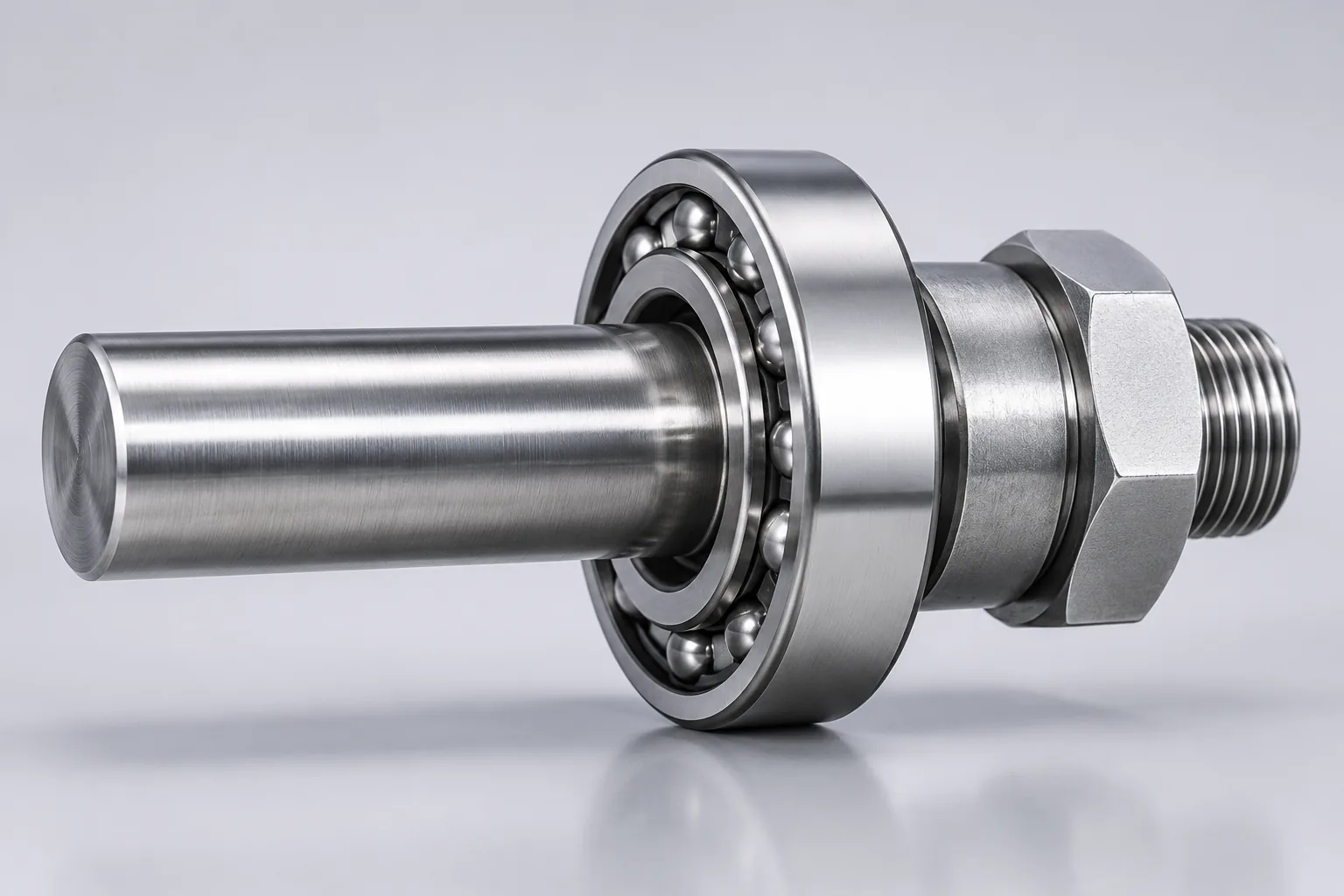
Matched angular contact pairs are supplied with axial clearance codes: CA for less than normal axial clearance, CB for normal axial clearance, and CC for greater than normal axial clearance. Those codes apply to an unmounted set arranged back-to-back or face-to-face and measured at zero measuring load, so they describe the pair before installation, not the running condition.
Not every bearing needs this adjustment. Deep groove ball bearings are normally selected by clearance grade and need no axial setting, which is one reason the two families should not share one mounting procedure.
Practical Selection Checklist
- Confirm the bearing type and whether axial play is fixed in the catalog or set during installation.
- Identify the dominant load direction and the axial and radial capacity the application needs.
- Check the speed limit and the contact-angle trade-off before choosing a wide-angle bearing.
- Account for interference fits, shaft and housing materials, and operating temperature when picking a clearance grade.
- Verify effective operating clearance, not only the catalog initial clearance.
- For tapered roller and angular contact arrangements, specify the adjustment method and the target axial play.
- Measure and record the final clearance or preload after assembly where the application allows it.
Work from the bearing manufacturer’s catalog data for the specific series and size at every step; general ratios are for estimation only.
Common Mistakes to Avoid
- Treating axial play and radial play as interchangeable, or applying one universal conversion ratio.
- Applying the cot α relationship from tapered roller bearings to deep groove ball bearings, or the cot(α/2) relationship in reverse.
- Ignoring clearance lost to interference fits and to thermal growth at operating temperature.
- Assuming a larger contact angle is always better, without weighing speed, radial capacity, and stiffness.
- Setting axial play on angular contact or tapered roller bearings without following the specified mounting adjustment procedure.
Conclusion
Axial play, radial play, and contact angle form one connected system: clearance defines how far the rings can move, contact angle defines the direction of the load path, and the bearing geometry decides how the two clearances trade against each other. Tapered roller bearings follow Δa = Δr cot α, single-row deep groove ball bearings follow Δa/Δr = cot(α/2), and neither expression may be transferred to another bearing family.
In practice, the safe sequence is to select the clearance grade from the specific bearing data, confirm the fits and operating temperature, then set and verify axial play or preload by the method the arrangement requires. When a target is unclear, work from the catalog data for that exact series rather than from a general ratio.
FAQs
Q1: What is the difference between axial play and radial play?
A: They describe the same clearance in different directions. Radial play is the total displacement of one ring relative to the other in the radial direction, while axial play is the displacement parallel to the bearing axis, with the other ring held fixed in both cases. Both are defined for an unmounted bearing under a specified measuring load.
Q2: Is axial play the same as end play?
A: Yes. Axial play, axial internal clearance, and end play name the same quantity: the total axial displacement of one ring relative to the other. The formal term is axial internal clearance; end play is the shorter workshop expression, often used for tapered roller and angular contact arrangements where the value is set during installation.
Q3: How do I convert radial play to axial play?
A: There is no universal conversion. For the tapered roller relationship, Δa = Δr cot α, so a 15° bearing gives about 3.73 times the radial play as axial play while a 40° bearing gives about 1.19 times. For a single-row deep groove ball bearing the ratio is cot(α/2). Use the formula that matches the bearing type, and treat it as a geometric estimate rather than a measured result.
Q4: Does a larger contact angle increase axial load capacity?
A: Generally yes. A larger contact angle tilts the load path toward the axis, which raises axial load capacity and axial stiffness. The trade-off is that smaller angles are usually better for high speed and radial capacity. The actual rating still comes from the catalog data for that bearing series, cage, and lubrication.
Q5: What contact angle is used in angular contact ball bearings?
A: Common angles are 15°, 25°, 30°, and 40°, and spindle ranges also use 17° designs. Smaller angles suit high speed and radial load, larger angles suit combined axial load. In common designation systems for standard single-row bearings, suffix B marks 40° and suffix AC marks 25°.
Q6: What do C2, CN, C3, C4, and C5 mean?
A: They are internal clearance grades ordered from tighter to looser as C1, C2, CN, C3, C4, and C5. CN is normal clearance, C2 is tighter than normal, and C3, C4, and C5 are progressively looser. ISO clearance groups map onto them as Group 2 = C2, Group N = CN, Group 3 = C3, Group 4 = C4, and Group 5 = C5.
Q7: Can axial play be zero or negative?
A: In theory a very slightly negative effective clearance can give maximum fatigue life, but life drops quickly as negative clearance increases and heat and wear risk rise. Practical selection therefore aims at a small positive operating clearance, after counting interference fits, temperature difference, and assembly variation.
Q8: How does an interference fit change radial play?
A: It reduces it. An interference fit expands the inner ring or contracts the outer ring, and the resulting radial clearance loss is roughly 70% to 90% of the interference amount, depending on bearing type, size, shaft, and housing. Check the operating clearance after fitting rather than relying on the unmounted value.