Quick Answer: Choose a cam follower by matching the mounting interface first, then verifying load, life, track rating, and maintenance against exact published data. Confirm stud or yoke mounting, thread system, outside diameter, width, and lubrication access before comparing ratings. Select the outer-ring profile for alignment, the internal design for load and speed, and the seal and material for the environment. Check static safety, relubrication, and tightening torque. A part that fits the space but not the track is not safe.
Choosing the right cam follower for your application starts before the load rating table. The part must fit the machine interface, survive the real load spectrum, and work with the track, lubrication, and maintenance plan. The sequence below follows the decisions that most often cause rework when skipped.
Understand What a Cam Follower Is and When It Fits
A cam follower is a stud-type track roller. A threaded stud replaces the inner ring, and the outer ring runs directly on a cam, guide, or track surface. The stud carries the radial load into the frame or bracket, while the outer ring provides the rolling contact. This is different from a conventional bearing that needs a fully supporting housing around its outer ring.
Size designation often follows the outside diameter D, not the bearing bore d. That difference matters when comparing a cam follower with a standard radial bearing. A 12 mm cam follower and a 12 mm bore bearing are not interchangeable by dimension alone.
Use a stud-type cam follower when the machine frame or cantilever bracket can be tapped and has enough stiffness to support the stud. If the application provides a separate shaft and yoke support, compare a yoke-type track roller or roller follower. Roller followers may use separable, non-separable, or double-row cylindrical designs, so confirm the mounting style before comparing ratings.
Map the Mounting Interface and Space Envelope First
Before comparing dynamic or static ratings, confirm the mounting style, stud thread, outside diameter, outer-ring width, total length, lubrication access, and support stiffness. A correct bearing rating is useless if the stud, thread, or lubrication port does not fit the machine.
Choose Stud-Type vs Yoke-Type Mounting
Stud-type cam followers mount through a threaded stud into a frame or bracket. They suit direct mounting where the frame can be tapped and the cantilever load is acceptable. Yoke-type track rollers or roller followers are preferable when the machine provides a separate shaft and yoke support. Check whether the machine can tolerate cantilever loading on the stud before selecting a stud-type part.
- Stud-type: direct threaded mounting to a frame or bracket.
- Yoke-type: separate shaft support with a yoke or housing.
- Roller follower variants: separable, non-separable, and double-row cylindrical types.
Verify Dimensions, Thread System, and Lubrication Access
Check stud diameter, outside diameter, outer-ring width, total length, thread size, and mounting-hole clearance. Confirm metric versus inch thread systems and replacement dimensions before ordering. Online selection filters can start at M2.5×0.45 thread and 5 mm outside diameter, but the exact machine envelope still controls the choice.
Relubrication access is part of the interface. Depending on series and size, a cam follower may have up to three relubrication positions: the stud head, the threaded end, and a radial passage through the stud or an adjacent component. Some sizes 35 and above can connect to centralized lubrication. KR 16 and 19 PPSKA cannot be relubricated. Do not specify a relubrication port unless the selected size and series actually provides it.
Define the Real Load Case, Including Shock and Track Reaction
Load selection must cover radial load, shock and vibration, static safety, minimum load, track hardness, and any axial component caused by misalignment. Do not size only by the bearing’s basic dynamic or static rating. Because the outer ring contacts the track over a small zone, the mating track may be the limiting element.
Calculate Dynamic Equivalent Load and L10 Life
Apply a load factor fW to account for shock and vibration instead of using average steady-state load. Basic dynamic load rating C is the radial load that gives a 10^6 revolution L10 rating life for a group of identical products. Obtain C from the exact part number, not from a series average.
For needle roller cam followers, the published life relationship is:
L10 = (C / P_C)^(10/3) × 10^6 revolutions
Use P_C as the dynamic equivalent load after applying the load factor. A practical load factor set is:
- 1 to 1.2: smooth motion without shock.
- 1.2 to 1.5: normal motion with moderate shock.
- 1.5 to 3: severe shock and vibration.
Use fW greater than 1 whenever the cam or track introduces impact, reversing load, or vibration. If the calculated life is close to the required life, verify the track rating and lubrication interval before accepting the size.
Check Static Safety, Minimum Load, and Track Load Rating
Check static safety against both the bearing static rating and the stud allowable load. The allowable static bearing load is the smaller of the maximum allowable static radial load F0r and the basic static rating C0. Dynamic load must not exceed the published maximum dynamic radial load Fr.
Static safety relationships are fS = C0 / P0 and fM = F0 / P0. Recommended minimum fS is 1 to 2 for normal load and 2 to 3 for shock load, assuming correct lubrication, mounting, and assembly.
Verify the track load rating separately. One KR40LL example lists a basic dynamic rating of 14.0 kN, a basic static rating of 22.8 kN, but a track load rating of only 3.85 kN. The track can therefore govern the selection even when the bearing rating looks generous.
Correct the rating when the track is softer than the published assumption. For lower track hardness, use CH = fH × C and C0H = fH0 × C0. Soft steel, aluminum, or an unhardened cam surface should not be given the full published rating.
For dynamic operation, check minimum load to keep the outer ring driven and avoid skidding or loss of contact. A common criterion is C0r,w / Fr below 60. Use the track manufacturer’s allowable contact load when it is available.
Select the Outer Ring Profile for Alignment and Contact
Choose a crowned or cylindrical outer-ring profile based on misalignment, shaft deflection, track flatness, and contact-stress tolerance. A crowned profile helps absorb minor misalignment and reduce edge loading. A cylindrical or flat profile can widen contact under good alignment, but it demands higher installation precision.
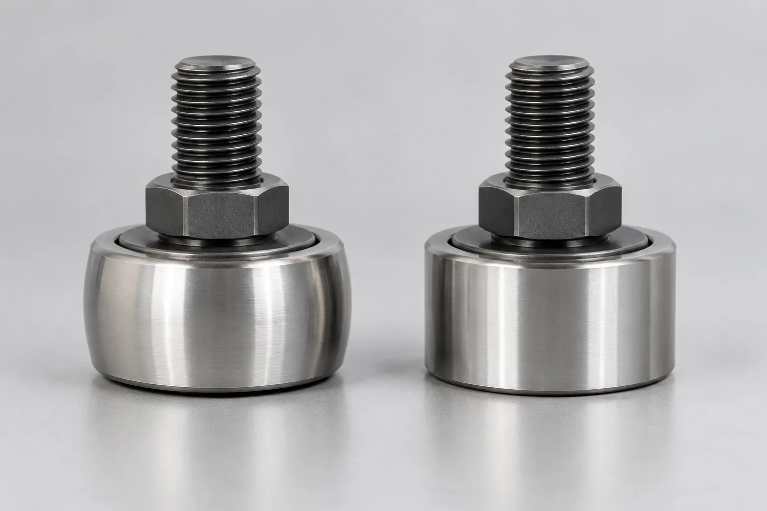
Suffix tables identify the running surface. Suffixes X, XA, XB, and PPXA indicate cylindrical running surfaces. Suffixes A, PPA, and PPSKA indicate improved crowned profiles. Use the manufacturer’s suffix table and contact-load table rather than guessing from a drawing.
- Crowned: use when frame deflection or mild misalignment is expected.
- Cylindrical or flat: use only when alignment and track flatness are tightly controlled.
- Contact load: confirm with the published table; a flat profile does not automatically increase allowable load.
Choose Internal Design and Size for Load, Life, and Speed
Compare caged needle, full-complement needle, and double-row full-complement cylindrical designs against load, speed, lubrication, and maintenance requirements. Higher load capacity often brings higher relubrication demand or a different speed limit.
Compare Caged Needle, Full-Complement Needle, and Double-Row Cylindrical Designs
Series naming usually signals the internal design. KR is a caged needle roller design, KRV is a full-complement needle roller design, and NUKR and PWKR are double-row full-complement cylindrical roller designs. Full-complement designs generally require more frequent relubrication than caged designs.
- Caged needle: suitable where speed and lubrication conditions favor a cage.
- Full-complement needle: higher load capacity, usually with higher relubrication demand.
- Double-row full-complement cylindrical: aimed at higher load capacity and stiffness.
Choose a full-complement design when load capacity is the dominant constraint and maintenance access exists. Do not choose it solely for load if relubrication access is poor.
Verify Speed Limits and Lubrication by Exact Part Number
Obtain the limiting speed from the exact part-number data sheet. Speed capability varies widely within one brand and series. For example, KR12T2LLH has a grease-lubricated limiting speed of 10,000 rpm, while the larger CRV64LL is listed at 2,200 rpm.
The KR12T2LLH example also shows why the full data set matters:
- Thread: metric M4×0.7.
- Outside diameter: 12 mm.
- Sealing: double-sealed.
- Outer ring: crowned.
- Dynamic rating: 2.17 kN.
- Static rating: 1.69 kN.
- Track rating: 725 N.
- Grease limiting speed: 10,000 rpm.
- Operating temperature: -40 to 120°C.
Do not estimate speed capability from the series name or outside diameter alone.
Match Sealing, Material, and Temperature to the Environment
Select sealing and material for contamination, coolant, washdown, humidity, cleanroom, and temperature exposure. Temperature limits differ by seal type, lubricant, cage, and manufacturer. Do not apply a series-level temperature range to every part number.
Suffix .2RS indicates NBR contact seals on both sides. PPA indicates PA66 axial sliding and sealing rings on both sides with an improved crowned outer ring. For contamination, coolant, or wet environments, compare double-sealed versions, then check the resulting speed and temperature limits.
Published temperature ranges can differ by variant. A general cam follower range may be -30 to +140°C, while PPA and PPSKA variants are limited to -30 to +100°C, and PWKR..2RS and PWKRE..2RS variants to -30 to +120°C. One manufacturer’s standard cam follower instructions state not to use the standard part at 80°C or higher; another manufacturer’s standard steel pages show -40 to 120°C. Do not mix limits across manufacturers or seal variants.
For corrosion resistance or low particle emission, compare carbon steel with 400-series stainless steel versions. Full stainless types may use symbol M and are positioned for cleanroom applications that need rust resistance and low particle generation. Confirm load and speed effects before substituting stainless for carbon steel.
Plan Lubrication and Maintenance Before Installation
Treat factory grease as an initial fill, not a lifetime guarantee. Periodic relubrication is usually required for full life. Set the interval from contamination, moisture, speed, temperature, and load.
Contamination, humidity, high speed, or temperatures above 70°C require more frequent relubrication. Light load, low speed, and clean conditions can allow longer intervals. Provide access to the selected relubrication position during machine design.
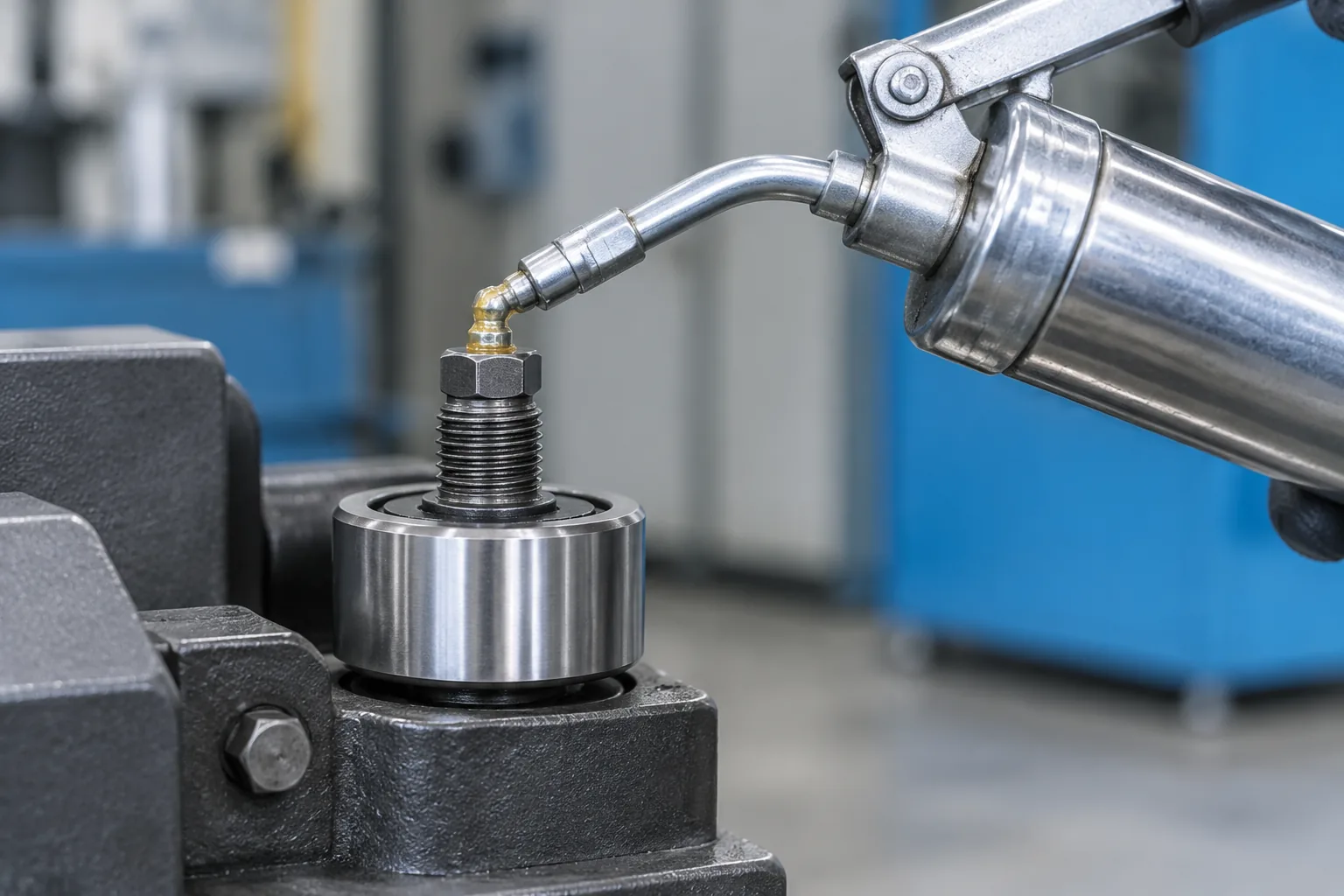
Small reciprocating motion needs special attention. Micro-oscillation can prevent lubricant from covering the rolling contact and can cause fretting. Use a grease with good fretting resistance and periodically rotate the roller at least one full turn to redistribute lubricant. Some part numbers cannot be relubricated; do not specify them for inaccessible long-life positions without confirming life.
Decide on Eccentric Adjustment and Axial Load Capability
Use eccentric-stud or eccentric-sleeve versions only when the machine needs position or preload adjustment. KRE, KRVE, NUKRE, and PWKRE series have an eccentric sleeve pressed onto the stud. CFH has a 0.25 to 1.0 mm offset between the stud mounting axis and the stud head axis, so rotating the stud adjusts position.
Do not use standard cam followers for continuous thrust load. If misalignment creates axial load, evaluate an axial-capable variant. CFN with a thrust ball is intended for axial load caused by mounting error, not for continuous thrust service. Do not substitute an axial-capable cam follower for a properly designed thrust bearing in continuous axial load.
Validate Mounting Stiffness, Fastening Torque, and Replacement Equivalence
Check frame, bracket, and bolt stiffness. Insufficient stiffness or precision concentrates load and can significantly reduce bearing performance. A high-load cam follower cannot compensate for a flexible bracket or a poorly aligned mounting face.
Use the exact part-number tightening torque and a torque wrench. Examples show the range: KR13T2LLH is listed at 2.0 N·m, while KR40LL is listed at 76 N·m. Do not scale torque from a similar-looking part number or from outside diameter alone.
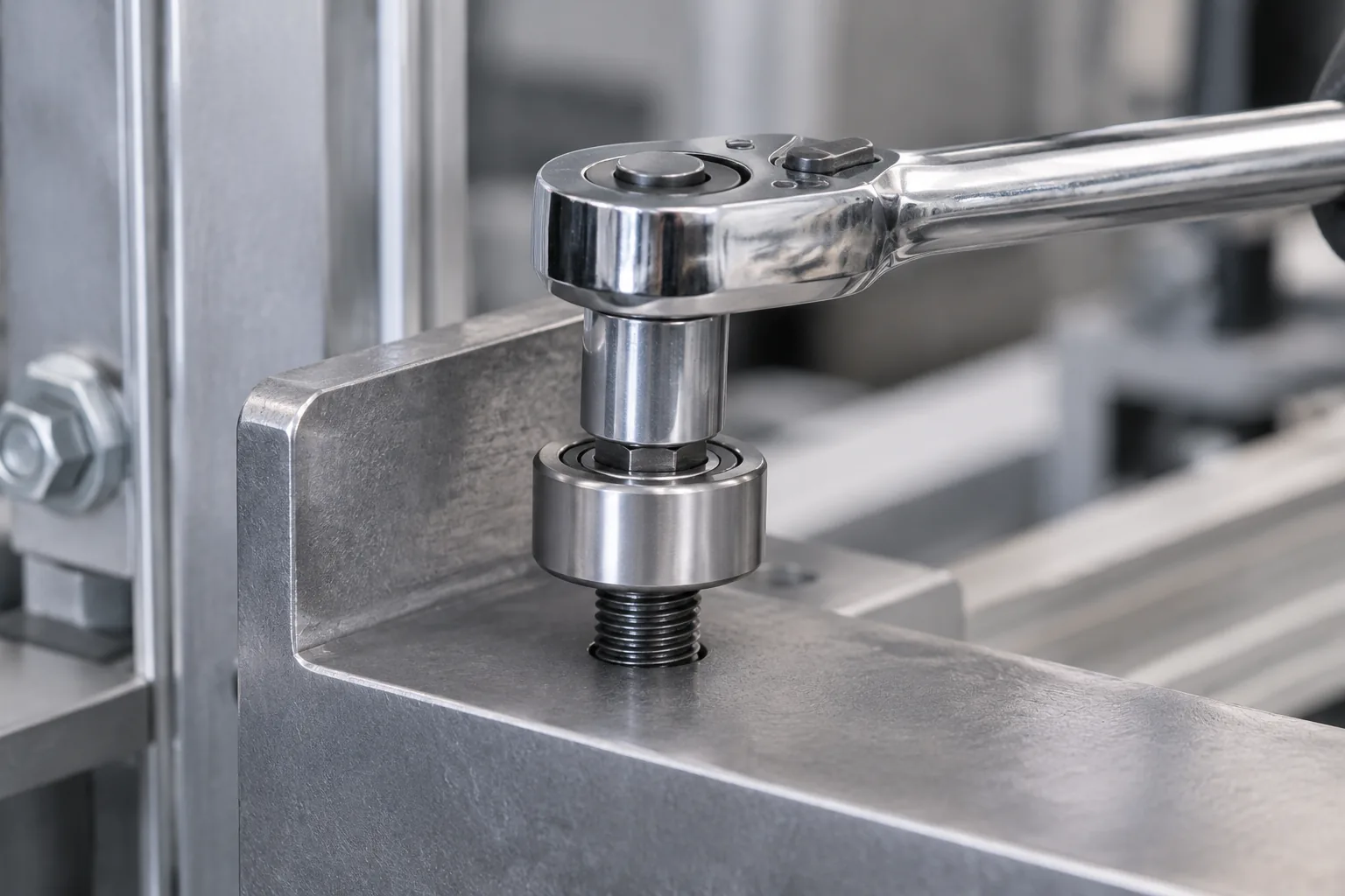
For replacements, confirm metric or inch thread, outside diameter, total length, mounting hole, lubrication interface, and load rating equivalence. Published series include metric KR, KRV, NUKR, and PWKR, plus inch CF and CFE designs. Confirm the thread system and mounting dimensions before ordering a replacement.
Use a Final Selection Checklist to Choose the Right Cam Follower and Validate in Service
Close the selection by tying the application, interface, load and life, track compatibility, internal design, speed, sealing and temperature, lubrication, adjustment, and mounting torque together. Then validate the assumption in service before full production release.
Final Checklist Items
- Application: cam, guide, or track motion; duty cycle; shock; misalignment; axial effects.
- Interface: stud or yoke; thread system; outside diameter; width; total length; mounting stiffness; lubrication access.
- Load and life: dynamic equivalent load; fW; L10 life; static safety fS and fM; minimum load; track load rating.
- Track: hardness; surface finish; alignment; contact stress; crowned or cylindrical profile.
- Bearing: caged, full-complement, or double-row; speed limit; seal type; material; temperature limit.
- Maintenance: relubrication interval; relubrication port; micro-oscillation mitigation.
- Installation: tightening torque; alignment procedure; replacement equivalence.
Complete the checklist with the exact product data sheet for the proposed part number. If a value is not published for that part number, do not infer it from a nearby size.
Pre-Production Validation
Run a pilot under the most severe expected load, speed, temperature, and contamination condition. Inspect outer-ring wear, track wear, seal condition, grease condition, and stud tightness after a defined interval. Monitor vibration and temperature during the pilot: vibration typically rises before damage becomes visible, while a temperature rise usually appears later. If wear or temperature exceeds expectations, adjust the relubrication interval or change the part-number choice. Use pilot results to confirm assumptions about shock, track hardness, and maintenance access.
Conclusion
How to choose the right cam follower for your application comes down to sequence: define the mounting interface, quantify the real load and track reaction, select the outer-ring profile and internal design, then match sealing, lubrication, adjustment, and installation to the machine. The bearing rating alone is not enough. Verify static safety, track load rating, speed, temperature, and relubrication access for the exact part number. Before release, confirm mounting stiffness and tightening torque, and run a pilot under the most severe expected condition.
FAQs
Q1: What is the difference between a cam follower and a track roller?
A: A cam follower is usually a stud-type track roller: the threaded stud replaces the inner ring and mounts directly into a frame or bracket. A track roller is a broader term and may use a separate shaft and yoke support. The mounting interface, not the roller shape alone, decides which type fits the machine.
Q2: Can I replace a cam follower with a standard bearing?
A: No, not by dimension alone. A standard bearing needs a supporting housing around its outer ring, while a cam follower outer ring runs directly on a cam or track. Outside diameter, stud thread, outer-ring profile, load rating, lubrication access, and track hardness must all match the application.
Q3: How do I calculate cam follower L10 life?
A: Use the published needle roller relationship L10 = (C / P_C)^(10/3) × 10^6 revolutions, with C from the exact part number and P_C as the dynamic equivalent load after applying the load factor fW. Check the result against the required life and the track load rating, because the track may limit service life before the bearing does.
Q4: Should I choose a crowned or cylindrical outer ring?
A: Choose a crowned profile when frame deflection or mild misalignment is expected, because it helps reduce edge loading. Choose a cylindrical or flat profile only when alignment and track flatness are tightly controlled. Confirm contact load with the published table; a flat profile does not automatically increase allowable load.
Q5: Are sealed cam followers suitable for high-temperature applications?
A: Only within the specific seal and lubricant limit. A general range may reach +140°C, but PPA and PPSKA variants are limited to +100°C, and some double-sealed variants to +120°C. One standard cam follower instruction set limits use below 80°C. Check the exact part number, seal type, grease, and cage before applying any temperature limit.
Q6: Can standard cam followers take axial load?
A: Standard cam followers are intended for radial load and should not be used for continuous thrust. If mounting error creates axial load, an axial-capable variant such as CFN with a thrust ball may be considered for that misalignment-induced load. It is not a substitute for a properly designed thrust bearing in continuous axial service.
Q7: How often should cam followers be relubricated?
A: Set the interval from contamination, moisture, speed, temperature, and load. Contamination, humidity, high speed, or temperatures above 70°C require more frequent relubrication; light load, low speed, and clean conditions can allow longer intervals. Confirm whether the selected part number can be relubricated at all before relying on a maintenance interval.
Q8: How do I choose between KR and KRV designs?
A: KR is a caged needle roller design and KRV is a full-complement needle roller design. Choose KR where speed and lubrication conditions favor a cage. Choose KRV when higher load capacity is the dominant constraint and relubrication access exists, because full-complement designs generally need more frequent relubrication.