Quick Answer: A slewing drive is an integrated rotary actuator that combines a slewing ring bearing with a gear drive. It supports axial, radial, and tilting loads while turning equipment under control, so it is more than a bearing or a gearbox alone. Worm and planetary designs serve different speed, torque, holding, and efficiency needs. Self-locking must be verified for the specific design and load, not assumed.
A slewing drive is often specified when a structure has to turn slowly under a heavy load and then hold position. It looks like a bearing with a gearbox attached, but the two functions are designed as one assembly. The practical questions are what sits inside it, how the load path works, and which checks decide whether a design will survive the duty.
Definition and Core Function
A slewing drive, also called a slew drive, is a compact rotary actuator: a gearbox and a bearing built as one unit. Its core job is to carry axial, radial, and tilting-moment loads while rotating the mounted equipment under control. The bearing supports the structure; the gear stage turns it. That combination is why a slewing drive is a subsystem, not just a bearing and not just a gearbox.
In a separate arrangement, a large slewing ring carries the load and a stand-alone gearbox drives a pinion. An integrated slewing drive packages the raceway, gearing, housing, seals, and motor interface in one envelope. That saves space and alignment work, but it also means the drive’s load rating, gear rating, and sealing must be evaluated together. Designs vary by gear type, enclosure, and axis configuration.
Slewing Drive vs. Slewing Ring Bearing
A slewing ring bearing supports load and allows rotation, but it does not create drive torque by itself. It provides the raceway and, in many designs, the gear teeth that a drive can use. Rotation still needs a motor and a gear stage.
A slewing drive adds gear reduction, a housing, and a motor interface to rotate the load. Selection depends on whether the application needs load support without actuation, or load support plus controlled rotation.
Key Performance Characteristics
Useful characteristics include high tilting moment capacity in a compact envelope, gear reduction, and controllable positioning. These drives are generally suited to slow-speed, high-torque rotation. Self-locking behavior depends on gear type and design, so it should not be assumed for every unit.
Exact torque, speed, and load ranges vary by model. Typical output speed, gear ratio, and load capacity are model-specific and must be checked against the published ratings for the exact drive.
Main Components of a Slewing Drive
A typical assembly includes a slewing ring, a worm or planetary gearset, a housing, seals, lubrication, and a motor mounting interface. The exact configuration varies by drive type and application. Understanding the components helps with selection, installation, and maintenance.
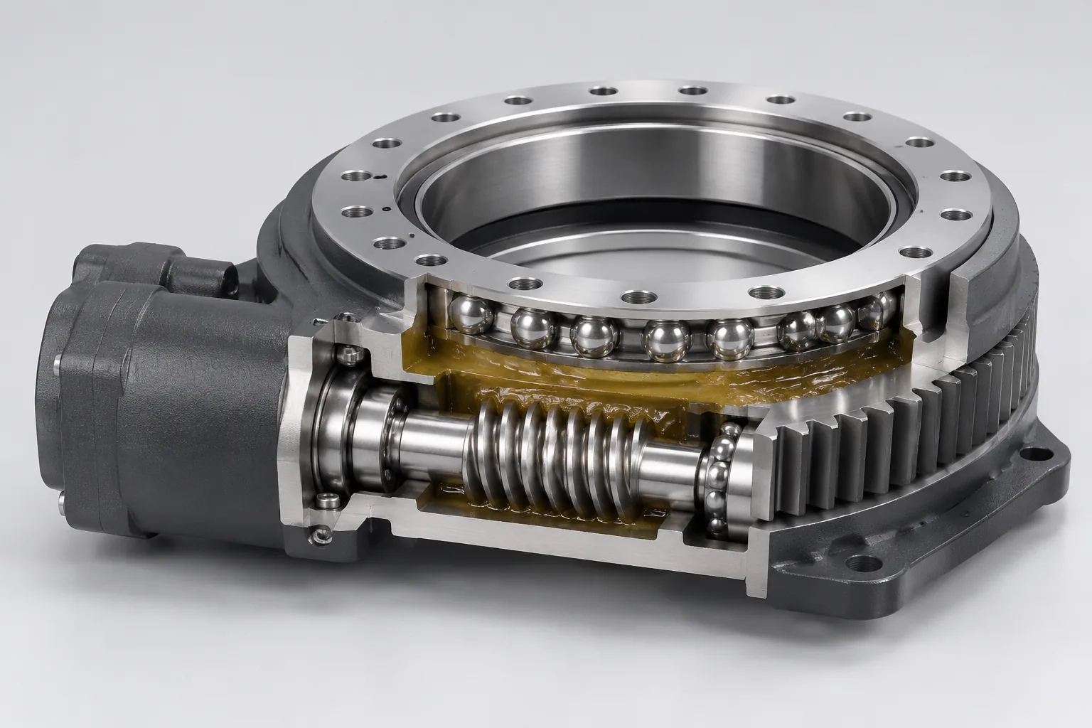
- Slewing ring bearing with raceway and, in many designs, gear teeth.
- Worm gear set, planetary gear stage, or another pinion arrangement.
- Housing and mounting interface.
- Seals and lubricant.
- Motor flange, shaft connection, and optional feedback devices.
Slewing Ring Bearing
The slewing ring provides rotational support and the raceway for axial, radial, and moment loads. It may include internal or external gear teeth depending on the drive design. Material, heat treatment, and raceway geometry affect load capacity and life; specific grades and hardness values require the manufacturer’s specification.
Gear Drive: Worm or Planetary
Worm gears offer high reduction ratios and possible self-locking. Planetary gears offer higher efficiency and torque density. Gear type influences back-driving, efficiency, speed, and holding requirements. Gear ratio is selected for the required output speed and torque.
Housing, Seals, and Lubrication
The housing protects internal components and provides the mounting interface. Seals retain lubricant and exclude contaminants. Lubrication method depends on orientation, duty cycle, and environment.
Motor and Control Interface
A slewing drive may be supplied with or without a motor. Motor flange and shaft interface must be compatible with the drive. Encoders or limit switches may be added for position feedback. Control integration affects positioning accuracy and safety.
How a Slewing Drive Works
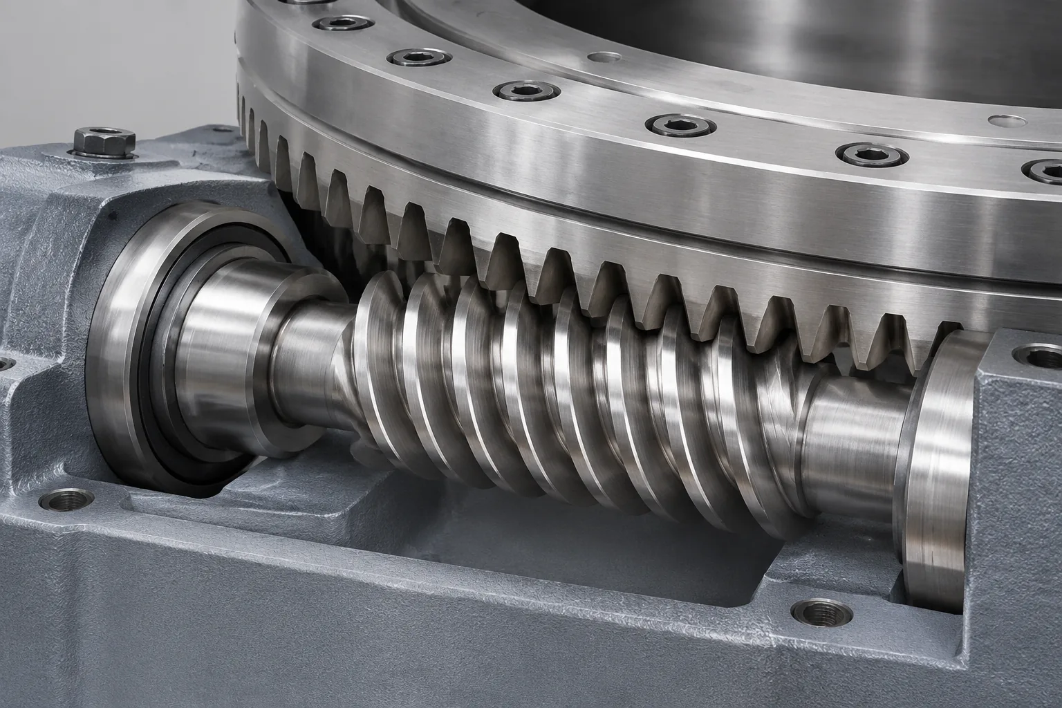
Motor input turns the worm or planetary gear, which rotates the slewing ring and the attached load. Gear reduction multiplies torque and reduces speed. The bearing raceway carries the load while allowing rotation.
Power Transmission Path
The power path runs from the motor through a coupling or input gear, into the worm or planetary stage, then to the slewing ring gear and the output flange or load.
- Motor input provides rotation and torque.
- The coupling or input gear transfers motion into the gear stage.
- The gear stage drives the slewing ring gear.
- The output flange or mounting surface turns the load.
The housing and one ring are normally fixed; the output ring and attached structure rotate. Efficiency depends on gear type, ratio, and lubrication.
Self-Locking and Back-Driving
Worm gear drives can be self-locking under certain lead angles, holding the load without a brake. Planetary drives generally back-drive and may require a holding brake. Self-locking depends on lead angle, friction, lubrication, and load conditions. Do not rely on self-locking for personnel safety without verification.
Rotation and Positioning Control
Position control is achieved through the motor, encoder, and controller. Backlash affects repeatability and positioning accuracy. Limit switches or hard stops may be needed for travel limits.
Common Types of Slewing Drives
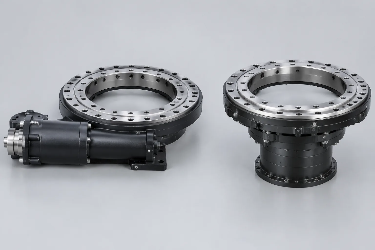
Types are classified by gear technology, enclosure, and axis configuration. Selection depends on load, speed, accuracy, environment, and cost. Common industrial designs use worm gear or planetary gear stages.
Worm Gear Slewing Drive
A worm gear slewing drive offers a high reduction ratio, a compact design, and often self-locking behavior. It is common in solar trackers and light-to-medium load positioning. Efficiency is lower than in planetary designs, so heat and lubrication must be considered.
Planetary Gear Slewing Drive
A planetary gear slewing drive offers higher efficiency and torque density, making it suitable for dynamic and high-load applications. It usually requires a brake for holding position. The design is more complex and potentially higher in cost than a worm drive.
Enclosed vs. Open Slewing Drive Designs
Enclosed designs protect gearing and lubricant from the environment. Open designs may allow easier inspection but require more maintenance. IP rating and sealing are key selection criteria.
Single-Axis vs. Dual-Axis Configurations
Single-axis drives rotate one axis. Dual-axis arrangements combine two drives for two-axis positioning. Dual-axis systems are used in solar trackers and robotic positioners. Mounting and control complexity increase with dual-axis systems.
Key Specifications and Selection Factors
Selection requires load analysis, duty cycle, speed, accuracy, environment, and life target. Published drive ratings provide torque, tilting moment, and limiting load curves. Safety factors depend on application standards and shock loading.
- Load case: axial load, radial load, tilting moment, and shock.
- Duty cycle and expected service life.
- Output speed, gear ratio, starting torque, and holding torque.
- Positioning accuracy, backlash, and repeatability.
- Environment: dust, water, temperature, and corrosion.
- Mounting orientation, control interface, and maintenance access.
Load Capacity and Tilting Moment
Axial load, radial load, and tilting moment must be compared with published ratings. Dynamic and static ratings differ; shock loads require higher safety factors. Load curves are application-specific and must be verified with manufacturer data.
Gear Ratio, Output Speed, and Torque
Gear ratio determines output speed and torque from motor input. Account for efficiency losses in the drive train. Verify starting, stall, and holding torque requirements.
Accuracy, Backlash, and Repeatability
Backlash affects positioning accuracy and oscillation. Preloaded or adjusted gear sets can reduce backlash. Repeatability depends on control, mechanical stiffness, and drive condition.
Environmental Protection and Duty Cycle
Consider IP rating, corrosion resistance, temperature range, and lubricant compatibility. Duty cycle affects thermal capacity and service life. Harsh environments may require special seals and coatings.
Typical Applications
Slewing drives are used where controlled rotation and load support are combined. Applications span renewable energy, construction, material handling, robotics, and industrial equipment.
Solar Tracking Systems
Single-axis and dual-axis trackers use slewing drives for slow, precise rotation. Self-locking worm drives are common for holding position, but self-locking still needs verification for the specific unit and load. Weather loads, backlash, and sealing affect tracker design.
Construction and Material Handling Equipment
Cranes, excavators, aerial platforms, and conveyors use slewing drives for swing and rotation. High shock loads and dust require robust sealing and adequate load ratings. Maintenance access is important for long service life.
Wind Turbines and Industrial Rotational Equipment
Slewing drives are used in yaw or pitch systems and industrial positioners. Wind-turbine duty requires high reliability and controlled backlash. Lubrication and sealing are critical in outdoor and remote installations. Specific wind-turbine use must be confirmed against manufacturer data and standards, not inferred from a general application list.
Robotics and Automated Positioning
Slewing drives provide compact rotary joints for robotic arms and turntables. Backlash and repeatability are key selection factors. Integration with servo control and encoders is common.
Installation, Lubrication, and Maintenance
Correct mounting surface, bolt torque, and alignment are essential. Follow the manufacturer lubrication schedule. Inspect seals, backlash, and gear wear periodically.
Mounting and Alignment Considerations
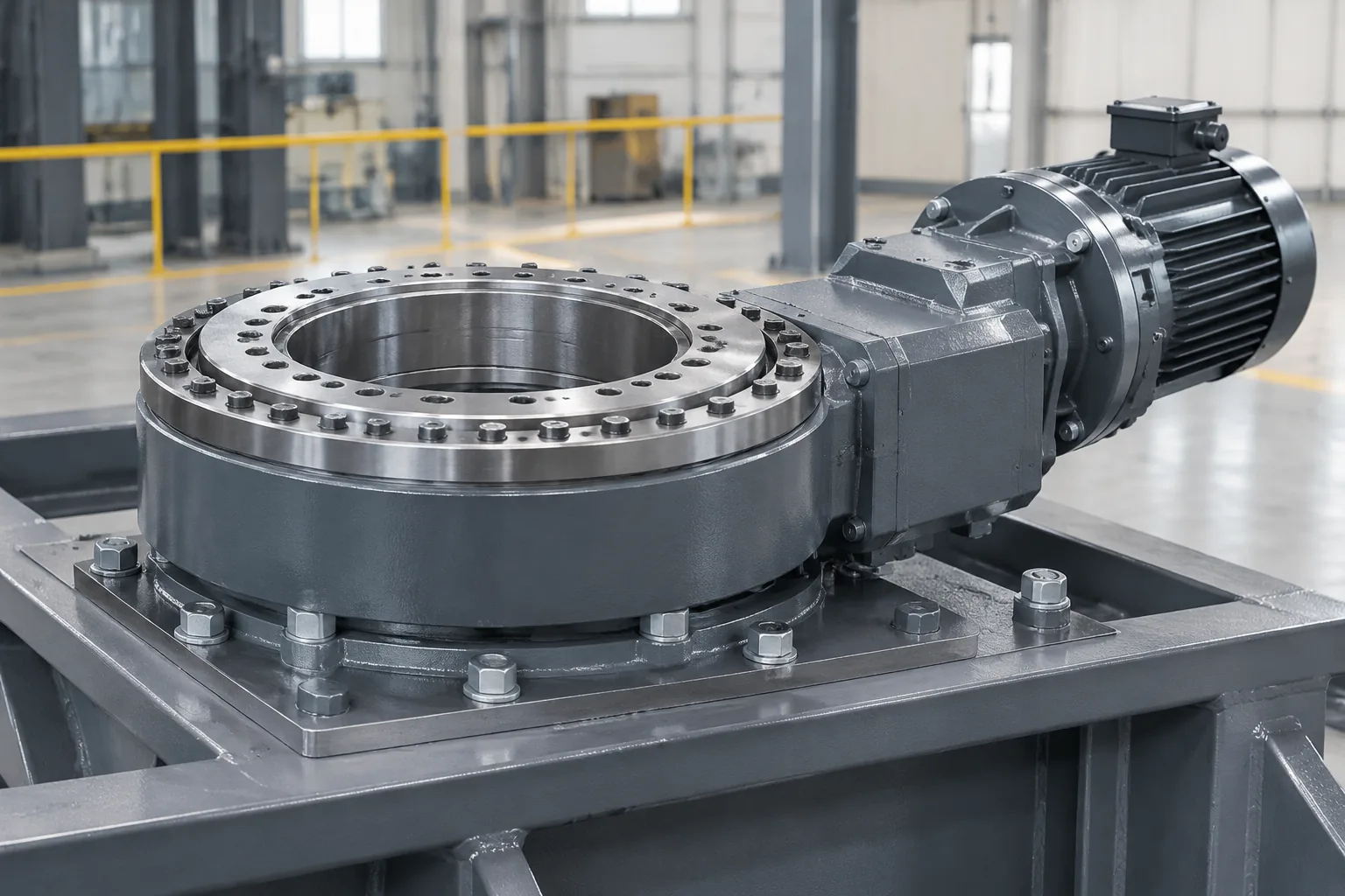
Mounting surface flatness and bolt strength affect load distribution. Avoid excessive side loads not accounted for in the rating. Use dowel pins or register fits where specified. Flatness and evenness can be assessed to DIN EN ISO 1101; the drawing and equipment specification define the acceptance limit.
Lubrication Requirements
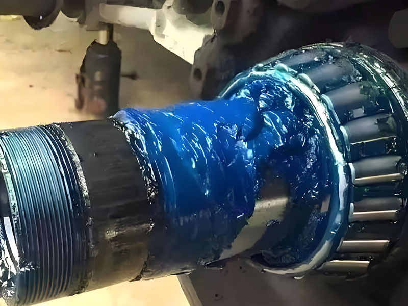
Grease or oil type depends on gear design and environment. Over-lubrication or mixing lubricants can cause problems. Temperature and speed affect lubricant choice. Lubricate both the raceway and the gear mesh as specified, and follow the drive maker’s fill level and relubrication schedule.
Inspection and Common Failure Modes
Common issues include seal leakage, lubricant contamination, gear wear, increased backlash, and bearing fatigue. Monitor abnormal noise, temperature, and backlash. Replace seals and lubricant as recommended.
On the bearing side, increased axial motion, subsidence, opened bearing clearance, or a change in tilt clearance can point to raceway wear. Raceway and gear wear, loss of preload, and insufficient bolt preload can contribute to these symptoms. Bearing fatigue can progress to cracks, spalling, or flaking. Pressure washing or cleaning-agent ingress can damage seals.
Establish reference readings at commissioning, then trend tilt clearance or subsidence over time. A practical inspection routine checks visible seals at least every six months and replaces damaged seals promptly. The equipment manual remains the final authority for intervals and methods.
Standards, Quality, and Testing
Relevant standards may cover bearing load ratings, gear quality, and safety; specific standard numbers require verification. Quality control includes material inspection, heat treatment, assembly, and load testing. Certifications depend on market and application.
Relevant Standards and Certifications
ISO, DIN, JB/T, or application-specific standards may apply; exact references require verification. ISO 15243 is one reference for classifying bearing damage. Mounting-surface flatness can be assessed to DIN EN ISO 1101. Certifications such as CE marking or ISO 9001 certification may be required by the market, but the actual requirement depends on the product, destination, and customer. Verify compliance with application safety requirements.
Load Testing and Quality Control
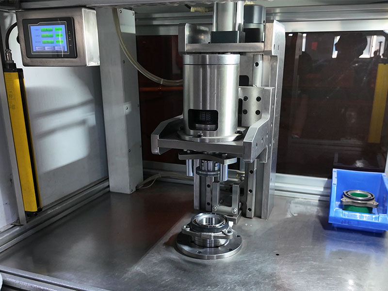
Static and dynamic load tests verify capacity. Backlash and rotation torque checks are common quality checks. Traceability of materials and processes supports reliability.
Conclusion
Slewing drive selection comes down to matching one integrated assembly to a specific rotary duty. The bearing must carry the load, the gear stage must deliver the needed speed and torque, and the housing, seals, and lubrication must survive the environment. Gear type changes efficiency, back-driving, and holding behavior, so self-locking should be verified rather than assumed. Before ordering, confirm the load case, duty cycle, mounting orientation, control interface, and maintenance access against published ratings.
FAQs
Q1: What is the difference between a slewing drive and a slewing ring?
A: A slewing ring supports load and allows rotation, but it does not provide drive torque by itself. A slewing drive adds a gear stage, housing, seals, and a motor interface so the load can be rotated under control. Choose a ring when the structure needs load support without actuation; choose a drive when controlled rotation is required.
Q2: How does a slewing drive work?
A: Motor input turns a worm or planetary gear, which drives the slewing ring and the attached load. The gear reduction raises torque and lowers speed, while the bearing raceway carries axial, radial, and tilting loads. The housing, seals, and lubrication keep the gear and raceway operating as one assembly.
Q3: Are slewing drives self-locking?
A: Some worm-gear designs can hold position without a brake under certain lead angles and friction conditions, but self-locking is not automatic. It depends on lead angle, lubrication, vibration, and load. Planetary designs generally back-drive. Do not rely on self-locking for personnel safety without verification.
Q4: What are typical applications for slewing drives?
A: Typical uses include solar trackers, cranes and excavators, aerial platforms, conveyors, wind-turbine yaw or pitch systems where confirmed by the turbine specification, industrial positioners, robotic arms, and turntables. The common requirement is slow, controlled rotation under load with a defined holding condition.
Q5: How do I select a slewing drive?
A: Start with the load case: axial load, radial load, tilting moment, shock, and duty cycle. Then match output speed, gear ratio, starting and holding torque, backlash, accuracy, environment, mounting orientation, and control interface to published ratings. Confirm the safety factor and the need for a brake before ordering.
Q6: How often should a slewing drive be lubricated?
A: Follow the equipment manual and the drive maker’s schedule. The interval depends on duty cycle, speed, temperature, contamination, and lubricant type. At each service, check lubricant condition and seals, and do not mix incompatible greases or overfill the housing.
Q7: Can a slewing drive be mounted vertically?
A: Many designs can be mounted in more than one orientation, but vertical mounting changes how lubricant reaches the raceway and gear mesh. Confirm the approved orientation, fill level, and sealing arrangement with the drive maker. Do not assume a horizontal mounting pattern applies unchanged.
Q8: What is backlash in a slewing drive?
A: Backlash is the small free movement between the gear teeth before they engage in the opposite direction. It affects positioning accuracy, repeatability, and oscillation. Preloaded or adjusted gear sets can reduce backlash, but the correct value depends on the drive design and application.
Q9: What loads can a slewing drive handle?
A: A slewing drive carries axial load, radial load, and tilting moment at the same time. Compare all three with the published ratings for the exact model and duty, including shock and fatigue. A single load figure is not enough to judge whether a drive fits an application.
Q10: Do slewing drives require a brake?
A: Worm drives may hold some loads through self-locking, but that is not a guaranteed safety brake. Planetary drives often need a holding brake. Use a brake when the application requires controlled holding, emergency stopping, or personnel safety, and verify the design with the drive maker.