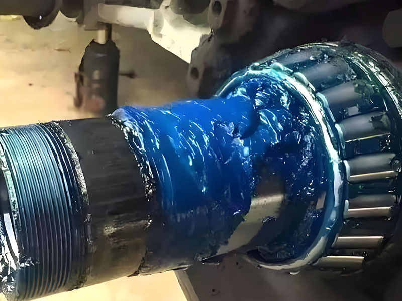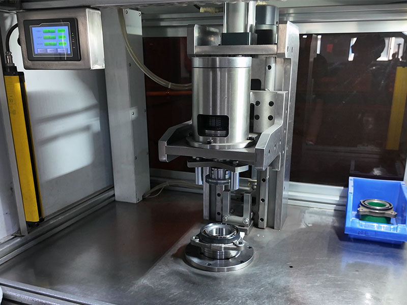
Quick Answer: Linear bearing noise failure diagnosis is a process of elimination, not a single test. Start with a repeatable baseline, localize when the noise occurs, verify lubrication and contamination control, check preload and alignment, then use vibration analysis before teardown. Confirm the failure mode from visible damage under ISO 15243:2017. Relubrication is a useful first test, but it does not prove the bearing is healthy if noise persists.
Linear bearing noise failure diagnosis begins with the understanding that a linear bearing can sound rough because the lubricant film is thin, because particles are being rolled through the block, because preload or alignment is wrong, or because a raceway has started to fatigue. The same noise can also come from a surface-quality defect that was present before service. The sequence below separates those possibilities in a practical order and keeps the evidence needed for a final root-cause decision.
Linear Bearing Noise Failure Diagnosis: Why Noise Alone Cannot Confirm a Failure
Noise is an output of the whole carriage system, not a label for one failure mode. Lubrication condition, contamination, mounting and preload, fatigue, and manufacturing or surface-quality defects can all raise sound levels. Fatigue cracks can start below the surface and reach the raceway until fragments break away as spalling or flaking; that damage changes bearing behavior and produces detectable noise and vibration. Raceway or rolling-element waviness, local defects on a ring or rolling element, and dirt particles can create similar signals.
ISO 15243:2017 is built primarily on visible damage characteristics. The standard cannot assign a root cause from noise by itself. If visual inspection cannot reliably identify the root cause, ISO 15243 calls for further investigation. A single absolute sound or vibration reading is also weak evidence on its own; trend comparison against an established reference value shows whether condition has changed.
Step 1: Establish a Repeatable Noise and Motion Baseline
Log sound, vibration, carriage speed, load, direction, position, and acceleration at fixed sensor points. The baseline must capture the operating conditions under which the noise occurs, because a quiet slow stroke and a noisy fast return are different test cases. Use the same sensor locations and operating conditions for later trend comparison, and compare current values with a known-good baseline or an established reference value.
Initial bearing defect signals can appear in a high-frequency band, with amplitudes too low to separate from lower-frequency machine vibration in a normal velocity or acceleration spectrum. Acceleration enveloping pulls those repetitive impacts out of the noise floor and places them at the defect frequency, so it is the practical choice when the standard spectrum looks unremarkable.
Step 2: Localize the Noise Event Before Inspection
Localization turns a general complaint into a testable condition. Determine whether the noise follows carriage position, direction reversal, speed, load, or temperature.
- Position-dependent noise points to local rail or raceway condition, contamination, and local damage.
- Direction-reversal noise points to preload, mounting error, and recirculation or loaded-zone transitions.
- Speed-dependent noise points to permissible travel speed and lubrication condition.
Spectral work on a recirculating linear bearing starts from the repetition rates implied by carriage speed and the guide’s internal layout, including rolling-element pitch, the circulation path, and loaded-zone transitions. Assigning a spectral peak to one raceway or rolling element requires the maker’s guide geometry. Standard rotating-bearing defect formulas do not apply unchanged to every linear guide.
Step 3: Rule Out Lubrication as the First Diagnostic Test
A major linear-guide maker names excessive travel speed and inadequate lubrication as direct causes of loud running noise in linear guideways. Its troubleshooting guidance says to verify the allowable travel speed and apply lubrication as directed. That makes lubrication the first practical test after the baseline, but it does not make lubrication the only possible cause.
Published LM guide lubrication options cover manual grease application, forced oil feed from an automatic pump, and oil-bath systems. Clean foreign matter off the rail before greasing, since it can get into the block. Then determine whether the noise changes after correct relubrication.
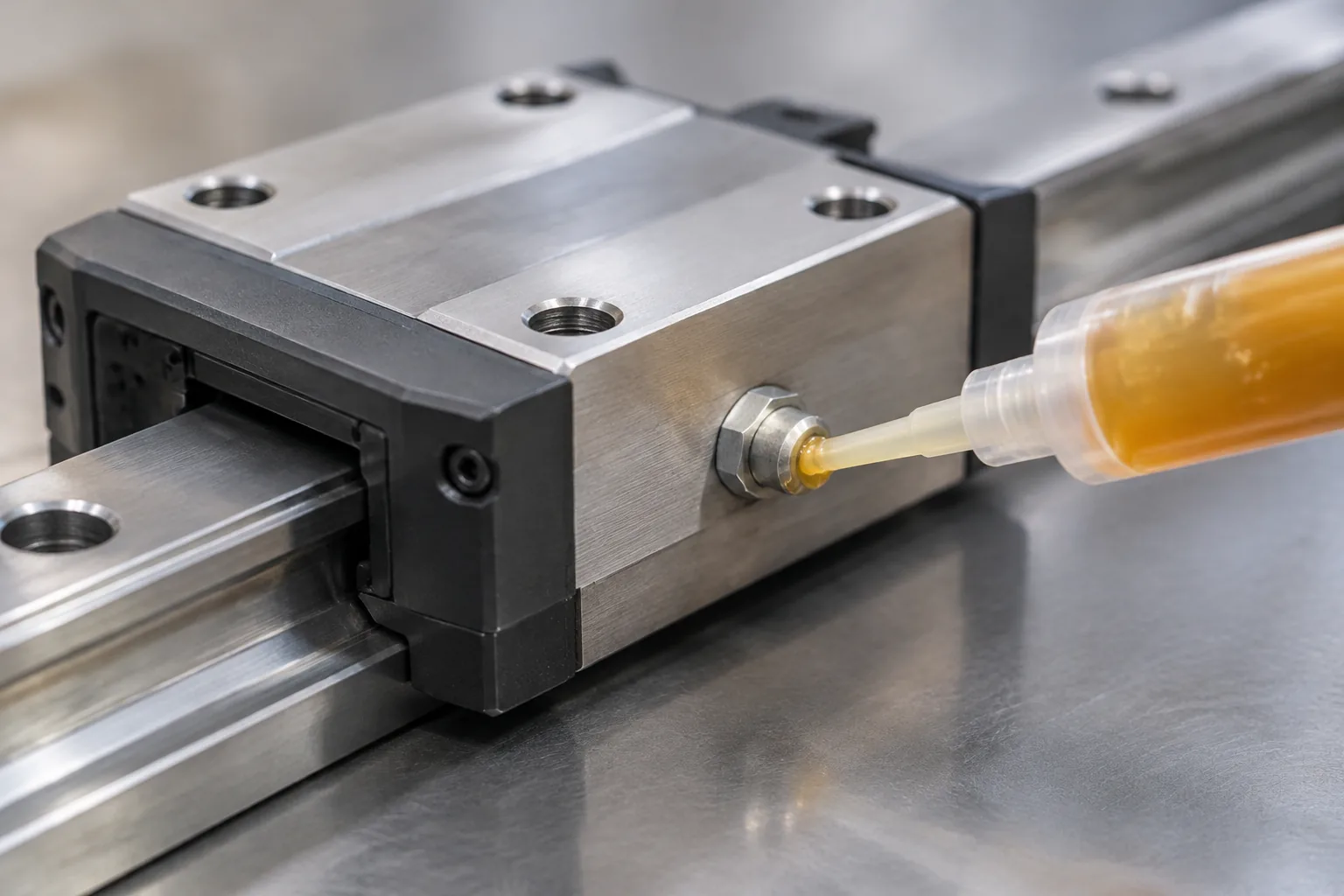
Published guidance sets a starting LM guide relubrication interval at roughly every 100 km of travel, or every three to six months. Operators must set the final interval and grease amount on the actual machine, since operating conditions and the environment change what is needed. Too little lubrication can lead to flaking and abnormal wear, and may eventually damage the guide.
Mounting orientation is part of the lubrication check. When the block is not horizontal, grease may not fully reach the raceway, and oil distribution through the block can depend on orientation.
Noise or resistance right after greasing does not by itself prove bearing damage. Sliding resistance can rise for a short time due to grease agitation; a break-in run may help the grease spread fully. Excess grease can also scatter after lubrication. Do not replace a bearing just because noise or resistance appears right after greasing.
Published bearing-failure analysis links more than 36% of premature bearing failures to poor lubrication; adding contamination takes the share well above 50%. Liquid contaminants lower lubricant viscosity, which can lead to metal-to-metal contact and rust on bearing contact surfaces. The resulting symptoms are higher temperature, wear, and noise.
Step 4: Inspect Contamination Control and Sealing
Maker guidance notes that dust or other debris entering an LM system causes abnormal wear or shortens service life, and can generate noise and vibration. Check rail surfaces, end seals, side seals, inner seals, the laminated contact scraper, bellows, rail-hole caps, and the lubricant for particles or liquid ingress.
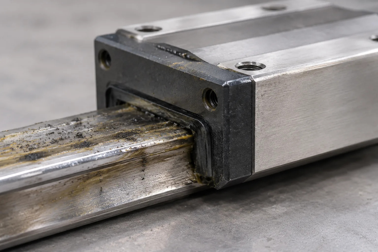
If liquid contamination is suspected, inspect housing seals. If liquid contamination is present, shorten the relubrication interval and supply smaller amounts of fresh grease more often.
Preserve lubricant and seal evidence before cleaning or replacement. Seal damage may stay hidden until the carriage or guide is inspected closely, so a quick external wipe is not a complete seal check.
Step 5: Check Mounting Accuracy, Preload, and Mechanical Alignment
Technical literature reports that four-point Gothic-arch contact can cause differential slip or ball spin when preload is present or mounting error is large. That sharply increases rolling resistance and can cause early abnormal wear. Assembly instructions also flag too much preload as a reason for unusually high displacement force, and advise checking that the chosen block preload is correct.
Measure mounting-surface accuracy, rail parallelism, bolt condition, preload, and displacement force. Mechanical checks should be performed separately from lubrication changes so the cause can be isolated. High force combined with noise supports checking preload and rail alignment rather than assuming lubrication failure alone.
Step 6: Analyze Vibration to Separate Bearing Defect from System Noise
Use time-waveform, FFT, narrow-band, and acceleration-envelope analysis. Acceleration enveloping strengthens repetitive impact signals and shows them at the defect frequency. Four standard diagnostic frequencies apply to rolling bearings: BPFO, BPFI, BSF, and FTF. Peaks at these frequencies or their harmonics are widely accepted as indicators of a defect in the matching bearing component.
| Frequency | Meaning | Equivalent notation |
|---|---|---|
| BPFO | Ball-pass frequency of the outer race | Ford = BPFO |
| BPFI | Ball-pass frequency of the inner race | Fird = BPFI |
| BSF | Ball-spin frequency | Fbd = 2 × BSF |
| FTF | Fundamental-train or cage frequency | Fc = FTF |
Calculating these frequencies needs the rolling-element count, rolling-element diameter, pitch diameter, contact angle, and rotational speed. Envelope analysis usually reveals characteristic bearing damage more clearly than a standard acceleration spectrum. With outer-ring raceway damage, the envelope spectrum shows BPFO and its harmonics.
For a recirculating linear bearing, work out the relevant repetition rate from carriage speed and the guide’s internal layout, such as rolling-element pitch, the circulation path, and loaded-zone transitions. You need the maker’s geometry before you can assign spectral peaks to a specific raceway or rolling element. Compare current vibration data with a known-good baseline. Never link spectral peaks to a linear bearing component without that geometry.
Step 7: Confirm Root Cause by Teardown and ISO 15243 Classification
Preserve evidence before replacing or cleaning the bearing. Running a bearing until it seizes can wipe out the evidence required to find the original failure mode and root cause.
ISO 15243:2017 carries the title Rolling bearings – Damage and failures – Terms, characteristics and causes. This is Edition 2, issued in March 2017, with 53 pages, and it was reviewed and confirmed in 2022. The standard groups in-service failure modes for rolling bearings made from standard bearing steels. It also defines their characteristics, visible appearance, and possible root causes.
The six principal damage categories are:
- Rolling-contact fatigue
- Wear
- Corrosion
- Electrical erosion
- Plastic deformation
- Cracking or fracture
Use visible load patterns and damage morphology for classification. If visual inspection cannot reliably identify the root cause, ISO 15243 calls for further investigation, which may include cross-sections, metallurgical microscopy, chemical analysis, and spectrographic analysis.
Bearing-investigation data published by a major maker names abrasive wear as the most frequent ISO failure mode, at 26%. Other modes in that dataset: surface-initiated fatigue accounted for 16%; moisture corrosion for 14%; adhesive wear for 7%; and current-leakage erosion for 7%; together they make up roughly 70% of the identified failures.
ISO 15243 cannot assign a root cause from noise by itself. Classification after teardown is what separates a confirmed mode from a diagnostic hypothesis.
Decision Guide: Noise Pattern to Next Check
| Noise pattern | Next check |
|---|---|
| Noise changes after correct relubrication | Check lubricant type, quantity, delivery point, interval, and mounting orientation. |
| Noise follows carriage position | Inspect local rail or raceway condition, contamination, and local damage. |
| Noise at direction reversal | Check preload, mounting error, and recirculation or loaded-zone transitions. |
| Noise with high displacement force | Check preload and rail alignment. |
| High-frequency impacts with envelope peaks | Investigate the rolling-contact defect using guide geometry. |
| Noise with heat, rust, or liquid ingress | Check contamination control, seals, and lubricant condition. |
| No clear trend | Preserve evidence and proceed to vibration analysis and teardown. |
Treat these as diagnostic hypotheses requiring confirmation by inspection, vibration data, or teardown.
Conclusion
Linear bearing noise failure diagnosis depends on sequence and evidence. A repeatable baseline shows whether the condition is changing; localization narrows the test; correct relubrication and seal inspection remove the most common service causes; preload and alignment checks catch mechanical errors; vibration analysis separates a rolling-contact defect from system noise; and teardown with ISO 15243:2017 classification confirms the mode. The safe next action is to preserve the lubricant, seals, rolling elements, and raceway before cleaning, then test one variable at a time. Do not replace a linear bearing on noise alone.
FAQs
Q1: Does relubrication stop linear bearing noise?
A: Correct relubrication is a first diagnostic test, but noise may persist if contamination, preload, mounting error, or damage is present. If the sound returns or does not change, move to seal inspection, alignment checks, and vibration analysis.
Q2: Can a linear bearing be noisy immediately after greasing?
A: Yes. Short-term resistance or noise can come from grease agitation, and a break-in run may help the grease spread fully. Excess grease can also scatter after lubrication. Do not replace the bearing just because noise appears right after greasing.
Q3: How often should linear guides be relubricated?
A: Published LM guide guidance sets a starting interval at roughly every 100 km of travel, or every three to six months. Operators must set the final interval and grease amount on the actual machine, since conditions and environment change what is needed.
Q4: Can vibration analysis locate linear bearing defects?
A: Envelope analysis and BPFO, BPFI, BSF, and FTF frequencies are accepted for rolling bearings, but a recirculating linear bearing requires guide geometry. You need rolling-element pitch, the circulation path, loaded-zone transitions, and carriage speed before assigning peaks to a raceway or rolling element.
Q5: When should a linear bearing be replaced?
A: Replace after confirmed damage classification and root-cause analysis, not on noise alone. Preserve the lubricant, seals, rolling elements, and raceway evidence, then classify visible damage under ISO 15243:2017.
Q6: What is ISO 15243?
A: ISO 15243 is the standard for rolling-bearing damage and failure terms, characteristics, and causes. The 2017 edition is Edition 2, issued in March 2017, runs 53 pages, and was reviewed and confirmed in 2022. Its six main categories are rolling-contact fatigue; wear; corrosion; electrical erosion; plastic deformation; cracking or fracture.