Quick Answer: A linear bearing design guide should start with the machine’s real duty: load direction and magnitude, moment loads, stroke, speed, acceleration, precision, stiffness, environment, and available space. Select a bearing type only after those requirements are fixed, then verify load rating and life, shaft and housing fits, lubrication and sealing, alignment, and installation. The goal is a guided linear motion system that carries load with predictable friction, wear, and service access, not the largest bearing that fits.
This linear bearing design guide is a practical design reference for selecting, integrating, and reviewing linear bearings. It focuses on design decisions rather than product promotion or brand comparison. The workflow is to define requirements, select a bearing type, verify load and life, design the shaft and housing, specify lubrication and sealing, and confirm installation and environment before drawings are released.
What Is a Linear Bearing and Where It Fits
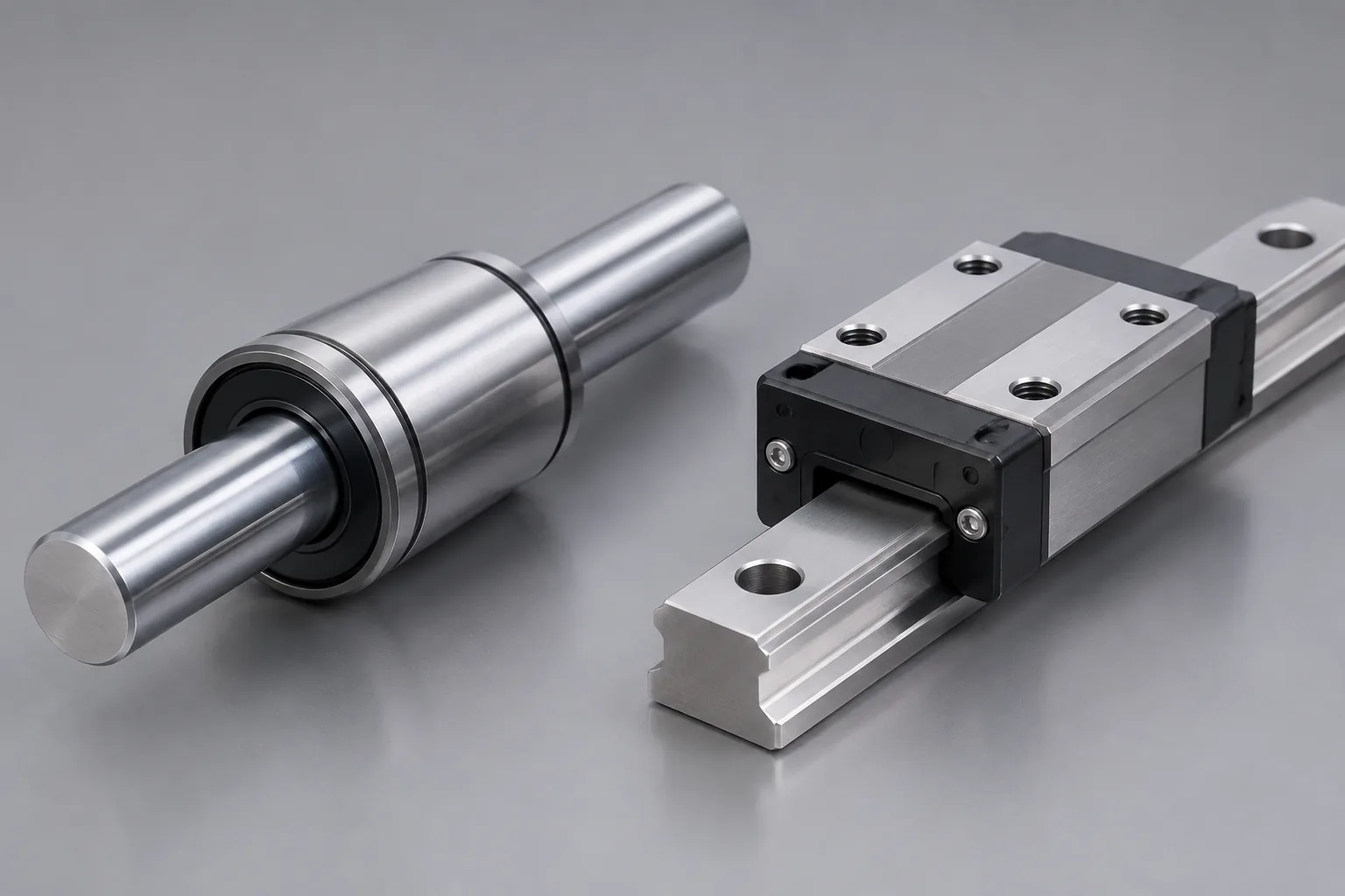
A linear bearing constrains linear motion between a moving part and a fixed part while keeping friction low. It may use rolling elements or sliding contact, and it may be supplied as a bushing, a carriage on a rail, or a shaft-based assembly. The term is often used broadly, so confirm which component the supplier means before comparing options.
Core Components and Motion Principle
Typical elements include the rolling or sliding elements, the shaft or rail, the housing or carriage, seals and wipers, lubricant, and the mounting structure. Load passes from the moving structure through the bearing interface into the fixed structure. Stiffness and alignment matter because local deflection or misalignment changes the load distribution and can raise friction, noise, and wear. Exact materials and geometry vary by type, so use the manufacturer’s data for a specific design.
Linear Bearing vs. Linear Guide, Bushing, and Ball Screw
These components solve different problems. Ball screws drive motion; linear bearings and guides support and guide the load. A bushing or shaft guide may be enough for a simple low-moment layout, while a linear guide may better resist moment loads and control stiffness. The comparison depends on load direction, stroke, precision, speed, environment, and mounting space.
| Component | Primary design role | Load and moment behavior | Friction and stiffness | Installation sensitivity | Contamination sensitivity | Use when |
|---|---|---|---|---|---|---|
| Linear ball bearing or bushing | Guides a shaft with rolling contact | Good for radial load; moment capacity depends on support spacing and bearing arrangement | Low friction; stiffness depends on preload and housing | Needs shaft alignment, finish, and fit control | Seals and wipers are important in dirty conditions | The layout uses supported shafts and the moment load is controlled |
| Linear guide | Guides a carriage on a rail | Can resist moment loads when the carriage and rail are sized for the duty | Stiffness and friction depend on preload and carriage design | Requires flat and parallel mounting surfaces | Seals and wipers are important; rail protection matters | The layout needs guidance, moment control, and a compact carriage |
| Plain bearing or bushing | Guides with sliding contact | Load capacity depends on material, length, and lubrication; moment capacity depends on arrangement | Friction is generally higher than rolling options; stiffness can be good | Needs lubrication or a dry-running material selected for the duty | Tolerance to dirt depends on material and seal design | Low-speed or simple motion where cost, space, and simplicity matter |
| Ball screw | Drives motion; does not replace guidance | Carries axial drive load; guidance and moment support come from bearings or guides | Efficiency and stiffness depend on screw and nut design | Needs support bearings and alignment with the guide | Protection is needed for the screw and nut | The machine needs controlled positioning or thrust, with separate guidance |
Linear Bearing Types and Selection Map
Common design-relevant types include linear ball bearings or bushings, shaft guides, linear guides, plain bearings, and roller-type linear bearings. The table is a starting map, not a rating table. Confirm detailed load, speed, precision, stroke, and environmental ratings in the manufacturer’s catalog for the exact series.
| Type | Typical design role | Load and moment notes | Stroke and layout | Precision and stiffness | Speed and friction | Environment and limits |
|---|---|---|---|---|---|---|
| Linear ball bearing or bushing | Guides a shaft with rolling contact | Radial load is the main design case; moment capacity depends on bearing spacing | Works with supported shafts and open or closed bushings | Preload and housing fit affect stiffness | Low friction; speed depends on lubrication, seals, and shaft finish | Seals and wipers are needed for dust and chips; confirm shaft hardness and finish |
| Shaft guide on round rail | Supports a carriage on one or more round shafts | Load sharing depends on shaft support spacing and carriage length | Long stroke is possible with supported shafts | Stiffness depends on shaft diameter, support spacing, and bearing preload | Speed depends on shaft alignment and lubrication | Shaft protection and alignment are critical outdoors or in dirty areas |
| Linear guide | Guides a carriage on a profile rail | Good moment control when carriage and rail are sized for the duty | Stroke is set by rail length; rail joints need care | Preload and rail mounting affect stiffness and accuracy | Seals, lubrication, and rail protection affect speed | Requires flat and parallel mounting surfaces; protect from chips and coolant |
| Plain bearing | Guides with sliding contact | Load capacity depends on material and length; moment capacity depends on arrangement | Suits short stroke or simple linear motion | Stiffness can be good; friction and wear depend on the material pair | Generally lower speed than rolling options unless the design is verified | Dry-running or lubricated versions have different contamination limits |
| Roller-type linear bearing | Uses rollers for rolling contact | Can be evaluated for heavier load or shock after rating check | Layout depends on roller orientation and rail or shaft support | Stiffness depends on preload and mounting | Friction is low; speed and heat need verification | Seals and lubrication are important; confirm contamination protection |
| Application signal | Candidate to evaluate first | Verify before release |
|---|---|---|
| High moment load and high stiffness | Linear guide with a wide carriage or dual rails | Moment rating, mounting flatness, preload, and drive alignment |
| Long stroke with supported shafts | Shaft guide or linear ball bearing on supported shafts | Shaft deflection, support spacing, seal protection, and lubrication |
| Dust, chips, or washdown | Sealed linear guide or protected bushing | Seal and wiper compatibility, corrosion resistance, and cleaning agents |
| Low speed and simple motion | Plain bearing or bushing | Material pair, lubrication, wear allowance, and alignment |
| Heavy load or shock | Roller-type linear bearing or heavy-duty guide | Static and dynamic ratings, shock margin, and mounting rigidity |
Define Design Requirements Before Selection
Selection without requirements is guesswork. Missing requirements cause over-design or under-design and often appear later as noise, wear, or alignment problems.
- Loads: load magnitude and direction, static, dynamic, shock, and moment loads where relevant.
- Motion: stroke and travel envelope, speed, acceleration, and duty cycle.
- Life and precision: required life, precision, stiffness, and noise target.
- Environment: dust, chips, coolant, moisture, corrosion, temperature, vacuum, cleanroom, vibration, and washdown.
- Integration: installation space, mounting structure, drive and control limits, and maintenance access.
Before selection, complete a requirement checklist that records the load case, motion profile, precision target, environment, and mounting space. If a requirement is unknown, mark it for confirmation instead of filling the gap with an assumed rating.
Load Rating and Life Calculation
The basic dynamic rating supports rolling-contact fatigue life under motion. The basic static rating checks permanent deformation under heavy or stationary load. Use the manufacturer’s rating definitions and the applicable rolling-bearing life method; do not compare ratings from different series without confirming the basis.
When radial, axial, and moment loads act together, calculate an equivalent load for each duty phase using the manufacturer’s load-direction factors. A single worst-case number is not enough if the cycle has different loads or speeds.
Use this calculation structure:
- Define the duty cycle and the load at each phase.
- Calculate equivalent load per phase.
- Compare with the dynamic rating and convert life to hours or travel using speed and stroke.
- Check the static rating for peak or stationary loads.
- Adjust for lubrication, contamination, installation quality, shock, and vibration.
Life estimates are valid only under the stated load, speed, lubrication, and environment assumptions. Shock, vibration, and contamination may require additional safety factors or application testing. If the duty is not well defined, use a conservative load case and confirm the result with the bearing supplier.
Stiffness, Preload, and Accuracy
Clearance, preload, and mounting rigidity set positioning accuracy and vibration behavior. Low clearance or preload can improve stiffness but may increase friction and heat. The right preload depends on required rigidity, heat, life, and drive capability. Confirm accuracy grades and preload values from the manufacturer’s data for the selected series.
Higher preload is not universally better. Excessive preload can increase friction and heat. A design review should check the preload against the drive, lubrication, thermal growth, and required life, not only against static stiffness.
Shaft, Housing, and Mounting Design
Shaft hardness, surface finish, tolerance, straightness, and support spacing are design variables. Housing fit, mounting flatness, and parallelism also matter. Shaft deflection and support layout change bearing load and life. Use design checks rather than universal tolerances. Confirm recommended hardness, roughness, fit, and alignment for the bearing type, load, precision target, and application.
A shaft that is stiff enough for static load may still deflect too much during acceleration. Check the complete support structure, including brackets and rail joints, not only the bearing.
Lubrication, Sealing, and Friction
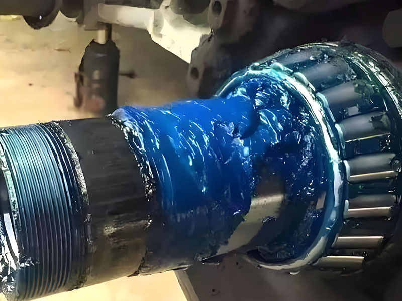
Lubrication reduces friction and wear and affects noise and life. Grease can help retain lubricant in many machine layouts. Oil may be selected where the bearing, seals, and application allow it, and where heat removal or speed requirements call for it. Dry-running or low-friction options need specific verification. Excess grease can raise friction and temperature, so fill quantity and relubrication should follow the bearing and application requirements.
Seals and wipers protect the bearing from dust, chips, moisture, and washdown. The seal choice must match the environment and the lubricant. Relubrication interval depends on speed, load, temperature, and contamination. Cleanroom, vacuum, food-grade, and high-temperature applications may require special lubricants or seals; verify compatibility before selection.
Speed, Acceleration, and Motion Profile
Speed and acceleration affect bearing selection, lubricant retention, heat, noise, and life. In automation layouts, check inertia, overhang, and stroke-end effects. Check the motion profile against bearing limits, not only average speed. Acceleration peaks, reversal, and vibration can be more demanding than the average value.
Confirm allowable speed and acceleration for the exact bearing, load, lubrication, installation accuracy, and duty cycle. If the profile includes rapid reversal or high overhang, review the bearing arrangement and mounting stiffness before release.
Environmental and Application Conditions
Design conditions include dust, chips, coolant, moisture, corrosion, temperature, vacuum, cleanroom, vibration, and washdown. Each condition changes bearing type, sealing, lubrication, material, and maintenance requirements. Standard bearings may not be suitable for vacuum, cleanroom, food, or corrosive environments without specific verification.
| Condition | Design response | Verification |
|---|---|---|
| Dust and chips | Seals, wipers, shields, and protected rail or shaft | Confirm seal and wiper compatibility |
| Coolant and moisture | Corrosion-resistant materials, sealed bearing, and drain path | Confirm chemical compatibility and cleaning method |
| Washdown | Sealed design, corrosion-resistant materials, and protected lubrication | Verify cleaning agents and seal rating |
| High temperature | High-temperature lubricant, suitable seal and clearance | Confirm temperature limits and thermal growth |
| Vacuum or cleanroom | Low-outgassing lubricant, sealed or dry-running design | Verify outgassing and particle requirements |
| Vibration and shock | Load margin, preload, and mounting rigidity | Confirm dynamic and static capacity |
| Corrosive atmosphere | Coated or corrosion-resistant components | Verify material and coating compatibility |
Installation, Alignment, and Running-In
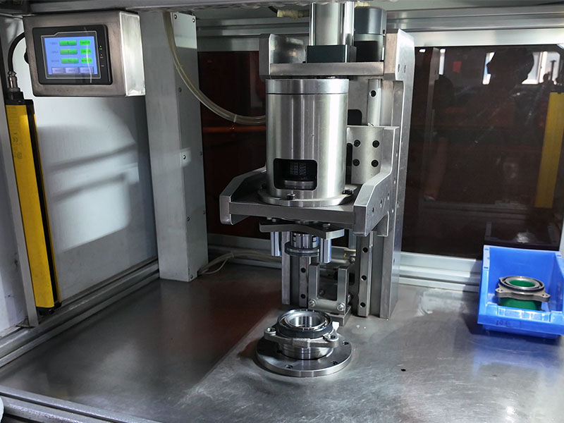
Plan the installation sequence: prepare mounting surfaces, align the shaft or rail, fasten in a controlled order, adjust preload if applicable, and run a verification check. Misalignment increases load, friction, noise, and wear. Use the manufacturer’s alignment tolerance and procedure for the bearing type and precision grade.
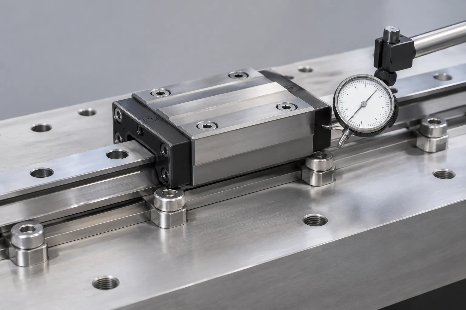
A running-in check should confirm smooth travel, temperature, noise, and fastener stability. Installation requirements vary by bearing type and precision grade. If the machine has multiple bearings on one shaft or rail, check that they share load as intended and that the mounting structure does not distort the bearing during fastening.
Common Failure Modes and Design Countermeasures
These are design-relevant failure modes, not a diagnosis from symptoms alone. A noise or looseness complaint can come from several causes; inspection of the bearing, shaft, seal, lubricant, and mounting is needed.
| Failure mode | Design countermeasure | Distinguish from |
|---|---|---|
| Contamination | Seals, wipers, shielding, and clean lubrication | Inadequate maintenance or a damaged seal |
| Insufficient or incompatible lubrication | Specify lubricant and relubrication practice | Wrong lubricant introduced in service |
| Misalignment | Control flatness, parallelism, and alignment procedure | Foundation or mounting movement |
| Overload | Load margin and equivalent load review | Shock or crash event |
| Fatigue | Dynamic rating and life review | Contamination or lubrication distress |
| Corrosion | Material and coating selection | Cleaning chemical attack |
| Seal damage | Protect the seal during installation and guard it in service | External damage |
Separate design causes from operation and maintenance causes before changing the drawing or the service schedule. For example, contamination can enter through a damaged seal, an open layout, or a cleaning practice that pushes debris into the bearing. The countermeasure belongs where the cause is found.
Linear Bearing Design Review Checklist
Use this checklist before releasing drawings or placing a bearing order.
- Requirements: load magnitude and direction, moment loads, stroke, speed, acceleration, duty cycle, life, precision, stiffness, noise, environment, and space.
- Type selection: compare the candidate types against load path, moment control, stroke, precision, speed, and contamination.
- Load and life: calculate equivalent load, compare dynamic and static ratings, and state the life assumptions.
- Stiffness and preload: confirm the accuracy grade, preload, mounting rigidity, and thermal effects.
- Shaft and housing: check hardness, finish, tolerance, straightness, support spacing, housing fit, flatness, and parallelism.
- Lubrication and sealing: specify lubricant, fill quantity, relubrication interval, seals, and wipers.
- Speed and acceleration: check the motion profile, inertia, overhang, reversal, and stroke-end effects.
- Environment: match the design to dust, chips, coolant, moisture, corrosion, temperature, vacuum, cleanroom, vibration, and washdown.
- Installation: define mounting surface preparation, alignment, fastening order, preload adjustment, and running-in checks.
- Verification: inspect travel, noise, temperature, fastener stability, and lubrication condition after assembly.
- Manufacturer data confirmation: ratings, preload, accuracy grade, shaft hardness and finish, housing fit, lubricant, seal, speed, acceleration, and alignment tolerance.
Conclusion
A linear bearing design guide is only useful if it turns machine requirements into verified choices. Define the duty first, choose the type that matches the load and moment path, confirm rating and life, then close the design through shaft and housing fits, lubrication and sealing, speed limits, environment, and installation. Complete the design review checklist and confirm catalog data for the exact bearing before releasing drawings. That sequence reduces rework and gives the maintenance team a system it can inspect and service.
FAQs
Q1: How do I choose between a linear ball bearing and a linear guide?
A: Choose based on the load path and moment control. A linear ball bearing or bushing can suit a supported shaft layout with limited moment load. A linear guide is often evaluated when the layout needs higher moment resistance, stiffness, or a compact carriage on a rail. Confirm load, stroke, precision, speed, contamination, and mounting space before selecting a series.
Q2: How is linear bearing life calculated?
A: Define the duty cycle, calculate equivalent load for each phase, compare with the dynamic rating, and convert life to hours or travel using speed and stroke. Check the static rating for peak loads, then adjust for lubrication, contamination, installation quality, shock, and vibration. Use the load and life method in this guide and state the assumptions.
Q3: What shaft hardness and surface finish are required?
A: There is no universal value. Required hardness, roughness, tolerance, and straightness depend on bearing type, load, precision target, and application. Confirm the recommended shaft specification in the manufacturer’s catalog and verify it on the drawing and incoming inspection. A finish that is too rough or a shaft that is too soft can accelerate wear.
Q4: How do I prevent contamination from damaging a linear bearing?
A: Use seals, wipers, and shielding matched to the dust, chips, coolant, or washdown condition; keep lubricant clean; and inspect seals during maintenance. In severe conditions, consider a protected guide or a different bearing arrangement. Do not rely on a standard seal for vacuum, cleanroom, food, or corrosive service without verification.
Q5: Can linear bearings be used in vertical or moment-loaded applications?
A: They can be evaluated for vertical or moment-loaded layouts, but the design must verify load direction, moment capacity, holding or braking, preload, mounting stiffness, and safety. A single bushing on a shaft may not control moment load well; a guide or a spaced bearing arrangement may be needed. Confirm the rating and arrangement with the manufacturer’s data.
Q6: What causes linear bearing noise or vibration?
A: Common causes include misalignment, insufficient or excess lubrication, contamination, preload that is too high or too low for the layout, shaft deflection, and mounting looseness. Noise or vibration is a symptom, not a diagnosis. Inspect the shaft, housing, seal, lubricant, and fastener condition before changing the bearing or the drawing.