Quick Answer: A timing belt pulley is the wheel that carries a timing belt in a synchronous drive. Toothed pulleys transmit torque through tooth engagement, while smooth guide or deflection pulleys route and support the belt without driving it. Correct selection depends on belt profile and pitch, tooth count, bore and hub style, flange arrangement, and the load and speed of the complete drive.
Matching a timing belt pulley to its belt and shaft looks simple until a replacement arrives with the right tooth count but the wrong pitch, or with a hub that will not clear the frame. This timing belt pulley guide covers the definition, working principle, construction, tooth profiles, materials, mounting options, selection inputs, installation, inspection and troubleshooting, so a buyer or technician can specify and fit the part with confidence.
The guidance here is general engineering support for specification and purchasing work. It does not replace the belt manufacturer’s installation instructions, the machine builder’s drawings, or an engineering review of a specific drive.
What Is a Timing Belt Pulley?
A timing belt pulley is a wheel used with a timing belt in a synchronous drive. The belt has teeth on its inner surface, the pulley has matching tooth spaces around its rim, and the two mesh so that rotation is transmitted at a defined ratio rather than through friction.
In engine timing systems and in machinery, the same part family covers two different jobs. Toothed drive pulleys carry torque from a shaft to the belt. Smooth guide, deflection or idler pulleys route the belt, hold wrap on other pulleys and take up slack without driving anything themselves. Both are commonly called timing belt pulleys.
The term is often confused with neighboring components, so it helps to separate them:
- Timing belt pulley – toothed or smooth wheel that works with a toothed belt; drive is synchronized.
- V-belt sheave – grooved wheel that drives through friction; some slip is normal and synchronization is not expected.
- Chain sprocket – toothed wheel for a roller chain; transmits torque through roller engagement and usually needs lubrication.
- Gear – toothed wheel that meshes directly with another gear; no flexible belt is involved.
Terminology also varies by region and industry. Pulley, sprocket, timing pulley, synchronous pulley, deflection pulley, guide pulley and timing idler can describe the same item, so the drawing and the belt profile matter more than the name on the label.
How a Timing Belt Pulley Works
Teeth on the belt enter the tooth spaces on the pulley and stay engaged through the wrap arc. Because the engagement is positive, one revolution of the driving pulley produces a defined number of belt pitches of travel, which is what makes the drive synchronous.
The load path runs from the shaft into the hub, through the pulley body to the teeth, and then into the belt. Every element on that path carries the same torque, so a hub that slips on the shaft or teeth that wear thin will limit the drive before the belt does.
Normal operation depends on two conditions: correct belt tension and correct alignment between the pulleys. With both in place, the belt stays seated and the teeth share load quietly. Overload, worn or damaged teeth, or too little wrap and engagement can let the belt climb out of the tooth spaces, which shows up as tooth jump or ratcheting under load.
Anatomy and Key Features of a Timing Belt Pulley
Most pulleys in this family share the same basic features, and each one changes how the part mounts or how the belt behaves.
- Toothed rim – the running surface; profile and pitch must match the belt.
- Body – the web between rim and hub; controls stiffness, weight and inertia.
- Hub – the boss that carries the bore; hub length sets how much shaft engagement is available.
- Bore – the shaft hole; pilot, finished, keyed or D-cut styles are common.
- Flanges – side plates that limit lateral belt movement.
- Keyway and set screws – positive drive and axial retention on a keyed shaft.
- Clamp or taper-lock features – friction mounting for quick, keyless fixing and easier angular adjustment.
- Surface finish – affects corrosion resistance, belt wear and, on aluminum parts, the need for an anodized or coated surface.
Two pulleys with the same tooth count can therefore differ completely in mounting behavior. Confirm bore, keyway, hub length and flange arrangement against the drawing before ordering, because a correct tooth profile on an incorrect hub still will not fit.
Common Types of Timing Belt Pulleys
Pulleys are usually grouped by the feature that decides interchangeability first, then by the features that decide mounting.
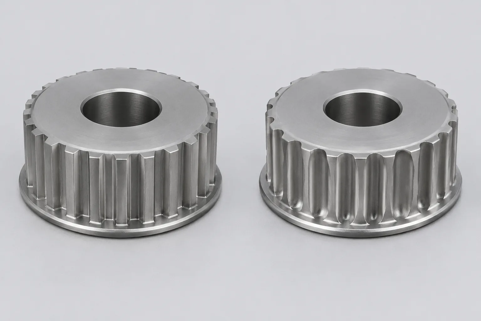
- By tooth profile family – trapezoidal and curvilinear families, each with its own belt series.
- By flange configuration – unflanged, single-flanged or double-flanged.
- By hub style – plain hub, stepped hub, or hubless and plate types.
- By bore style – pilot bore, finished bore, keyed bore, D-cut bore, or clamp and taper-lock mounting.
- By material – aluminum, steel, stainless steel or engineering plastic.
- By manufacturing method – machined from bar or blank, or formed and then finished.
Different tooth profile families are generally not interchangeable, even when the tooth count and outside diameter look close. Any recommendation also depends on belt profile, load, speed, environment and shaft mounting requirements, so a type name alone is not a specification.
Tooth Profiles, Pitch, and Standards
Four values decide whether a pulley and belt will work together: the tooth profile, the pitch, the tooth count and the resulting pitch diameter.
Pitch is the distance between repeating tooth features, measured along the pitch line. Pitch diameter, not outside diameter, is the value used for ratio and belt length calculations, and it follows from the pitch and the tooth count.
- Profile – the shape of the tooth space; must match the belt tooth shape.
- Pitch – the spacing of the teeth; must match the belt pitch.
- Tooth count – sets the pitch diameter and therefore the speed ratio.
- Pulley width – must be wide enough for the belt width in use.
Published profile families follow recognized standards, but nominal interchangeability across brands or standards should be verified rather than assumed. Mixed-brand belt and pulley combinations in particular may need profile and tolerance checks against both manufacturers’ data before the drive is assembled. Confirm the profile designation directly with the belt supplier instead of relying on a general table.
Materials, Coatings, and Manufacturing
Material choice trades strength against weight, inertia, corrosion resistance, machinability and cost.
| Material | Typical strengths | Points to watch |
|---|---|---|
| Aluminum | Low weight and inertia, good machinability, easy to anodize | Lower stiffness than steel; bores and threads need care |
| Carbon steel | High strength and stiffness, stable under load | Needs a protective finish in damp or washdown areas |
| Stainless steel | Corrosion resistance in wet or chemical environments | Higher cost and different machining behavior |
| Engineering plastic | Light, quiet running, non-magnetic, self-lubricating tendency | Lower load and temperature capability than metals |
Finishes such as anodizing, plating or black oxide are chosen for corrosion resistance and appearance, and they can affect bore fit if the coating thickness is not accounted for. Do not accept a load rating or tolerance figure without a documented value for that exact part; ask the supplier for the drawing and the material specification for the batch.
Critical Selection Parameters
Selection starts with the belt, not the pulley. Collect these inputs before requesting a quotation:
- Belt profile and pitch, taken from the belt marking or the machine drawing.
- Tooth count, which fixes pitch diameter and speed ratio.
- Pulley width, matched to the belt width.
- Bore and hub requirements, including keyway, hub length and clamping method.
- Torque and load, including shock loads and starting torque.
- Speed and duty cycle, including starts per hour and reversing operation.
- Environment: temperature, dust, moisture, washdown and chemical exposure.
- Alignment and service life expected from the drive.
Tooth count and pitch diameter set the speed ratio and, together with center distance, the belt length. Load capacity belongs to the whole drive system, not to the pulley on its own: belt width, tooth engagement, shaft stiffness, bearing support and tension all share the duty. Confirm the rating with the belt manufacturer and the pulley supplier, and keep a margin for shock and misalignment rather than working at a calculated limit.
Bore, Hub, and Shaft Mounting Options
The mounting method decides how much torque the joint can carry and how easy the pulley is to align and remove.
- Pilot bore – undersized bore for finishing to the shaft size; flexible but needs machining.
- Finished bore – ready to fit a stated shaft diameter.
- Keyed bore – positive torque transfer through a key; needs a matching keyway in the shaft.
- D-cut bore – flat on the bore for a grub screw or matching shaft flat.
- Set-screw mounting – simple axial retention; relies on screw torque and a flat or key.
- Clamping or taper-lock mounting – friction grip with even clamping; easier angular adjustment and removal.
Bore size, keyway dimensions, hub length and fastener type together decide mounting security and running runout. The chosen method has to match the shaft diameter, the torque to be transmitted, the access available for tightening, and the maintenance plan. Check shaft and bore tolerances before installation; a pulley that needs force to slide on is already a poor fit, and a bore that is too loose will slip and wear the shaft.
Flanges and Belt Tracking
Flanges are the side walls on a pulley rim. Their job is to limit lateral belt movement when the belt tries to run off the edge, usually during starts, reversing or slight misalignment.
Whether a pulley needs one flange, two flanges or none depends on pulley orientation, belt width, misalignment risk and the layout of the drive, and the belt and pulley manufacturer’s guidance should decide it. A common arrangement flanges the smaller pulley and leaves the larger one plain, but the correct choice for a specific drive has to come from that drive’s documentation.
Flanges are not a substitute for correct alignment and tension. A belt that is constantly rubbing a flange is reporting a misalignment or tension problem, and continued running will wear both the belt edge and the flange.
Installation, Alignment, and Tensioning
Preparation prevents most installation faults. Inspect the new pulley for tooth damage and flange condition, clean the shaft and bore of burrs and contamination, verify the belt profile against the pulley, and check that all mounting hardware is present and correct.
Align the pulleys so that the shafts are parallel and the pulley faces sit in the same plane. Angular misalignment usually comes from non-parallel or skewed shafts, worn bearings or a bracket that has moved, and it shows up later as edge wear, noise and flange rubbing. Fit the pulley without force: a press, gentle heat or a proper puller used on the correct surfaces is acceptable, while hammering on the rim or hub is not.
Set belt tension to the belt manufacturer’s specification for that belt and drive. There is no safe generic rule, because the correct value depends on belt section, span length and load. Too little tension allows tooth jump under load; too much tension loads the shafts and bearings and can produce noise from the timing belt area after installation.
After the first run-in period, recheck fastener tightness, pulley alignment and belt tension, and re-torque fasteners to the value given for the machine. Record the settings so the next service starts from a known baseline.
Maintenance and Inspection
Inspection is mostly visual and tactile, and it is quick when the drive is already open for a belt change.
- Tooth wear – flattened, hooked or polished tooth flanks on the pulley.
- Belt debris – black dust or rubber build-up in the tooth spaces.
- Flange rubbing – polished or worn flange faces and frayed belt edges.
- Bore slip – fretting marks, rust streaks or a polished shaft under the hub.
- Noise and vibration – squeal, chirp or rumble that changes with speed or load.
- Loose fasteners – set screws, clamp screws or taper-lock screws that have lost torque.
Worn pulley teeth will damage a new belt, so evaluate the pulleys whenever the belt is replaced and renew any part with visible tooth wear, bore damage or a worn flange. Follow the machine builder’s or belt manufacturer’s maintenance interval rather than a fixed rule of thumb, because intervals depend on duty cycle and environment.
Troubleshooting Common Timing Belt Pulley Problems
Use a symptom-first checklist, and treat each entry as a possible cause to eliminate rather than a verdict.
| Symptom | Possible causes | Checks |
|---|---|---|
| Belt runs off the pulley | Misalignment, insufficient flange support, uneven belt tension, damaged flange | Shaft parallelism, pulley face alignment, flange condition, tension on both sides |
| Noise from the belt area | Tension too high or uneven, misalignment, worn guide or tensioner pulley, contamination | Belt tension after installation, pulley smoothness, bearing play, foreign material |
| Tooth jump or ratcheting under load | Low tension, worn teeth, insufficient wrap, overload, wrong profile | Tooth condition, wrap arc, drive load, profile match to the belt |
| Premature tooth wear | Profile mismatch, misalignment, abrasive dust, overload | Belt and pulley profile match, alignment, environment, duty |
| Pulley slips on the shaft | Undersized or worn bore, loose set screw, missing key, insufficient clamp torque | Bore and shaft fit, key and keyway, fastener torque |
| Flange wear | Persistent misalignment, belt tracking to one side, wrong flange arrangement | Alignment in both planes, flange pairing, belt width |
Diagnosis has to consider the whole drive, including the belt, both shafts, the bearings and the driven load. A pulley that looks worn may be the victim of a misalignment or overload problem elsewhere, and replacing it without correcting the cause simply repeats the failure.
Applications and Use Cases
Synchronous belt drives appear wherever a defined motion relationship matters more than raw torque density. Typical areas include factory automation and linear axes, conveyors, packaging machinery, printing and labeling equipment, machine tools, and engine timing and accessory drives on vehicles.
Suitability depends on the load profile, speed, environment, duty cycle and the positioning accuracy required. A drive that runs continuously at steady load and a drive that reverses frequently with shock loads will not use the same pulley construction, even at the same torque. Treat any example here as illustrative; a specific application needs its own engineering verification before a part is specified.
Timing Belt Pulley vs Other Power Transmission Components
| Component | Synchronization | Slip behavior | Lubrication | Typical fit |
|---|---|---|---|---|
| Timing belt pulley | Positive, through tooth engagement | No slip in normal operation; tooth jump under fault conditions | Usually dry running | Medium loads over longer center distances, quiet running, low maintenance |
| Gear | Positive, through direct tooth mesh | No slip | Lubricated | High torque in compact center distances |
| Chain sprocket | Positive, through roller engagement | No slip | Lubricated | High load, harsh environments, high temperature |
| V-belt sheave | Friction drive, not synchronized | Controlled slip possible under overload | Usually dry running | Simple, tolerant of misalignment, lower cost |
The practical difference is that a timing belt pulley combines geared timing accuracy with the layout freedom of a belt: the shafts can sit far apart, the drive runs quietly and it needs no oil. Where torque density or shock resistance matters most, gears and chains keep the advantage.
Specification and Buying Checklist
Give the supplier the complete drive description, not just a part name. The following inputs prevent most ordering errors:
- Belt profile and pitch, plus the belt series in use.
- Tooth count and required pitch diameter.
- Pulley width and belt width.
- Bore diameter, keyway or D-cut dimensions and bore type.
- Hub type and hub length, with any clearance limits.
- Flange requirement and flange position.
- Material and surface finish, including any corrosion requirement.
- Quantity, marking requirement and application notes such as load, speed and environment.
Before ordering, confirm interchangeability with a drawing rather than a catalogue name, and state clearly whether the part replaces an existing item so that profile and tolerance can be compared. On receipt, check tooth form, bore, keyway, flange condition and part markings against the confirmed drawing before the pulley goes into the drive.
Conclusion
A timing belt pulley is a small part that carries the whole duty of a drive through a short length of tooth engagement, so the specification has to be right on the first order. Match the belt profile and pitch first, then fix the tooth count, pitch diameter, bore, hub and flange arrangement, and settle material and finish against the environment.
Installation matters as much as selection: parallel shafts, aligned pulley faces, clean bores, a pulley fitted without force, and belt tension taken from the belt manufacturer’s specification. When a drive becomes noisy or starts tracking to one side, inspect the complete system before replacing parts.
For a specific drive, send the operating details and, where available, the original drawing to the pulley supplier so that profile, tolerances and mounting features can be confirmed before production.
FAQs
Q1: What is the difference between a timing belt pulley and a timing belt guide pulley?
A: A timing belt pulley is the general term for a wheel used with a toothed belt, while a guide pulley – also called a deflection or idler pulley – is a smooth pulley in the same system that routes the belt and holds wrap without driving anything. On a driven shaft the pulley carries teeth and transmits torque; a guide pulley supports and redirects the belt.
Q2: How do I identify the correct replacement pulley?
A: Read the markings on the old part, count the teeth, measure the pitch, the outside diameter, the bore and the flange arrangement, and match the belt profile. Compare the results with the supplier’s drawing rather than a similar-looking catalogue entry, because two pulleys with the same tooth count can still differ in bore, hub length and flange position.
Q3: Can I replace just the pulley and keep the old belt?
A: A worn pulley and a worn belt usually belong together. Worn teeth damage a new belt, and a stretched or contaminated belt will not run correctly on a new pulley, so inspect the belt, both pulleys and any guide or tensioner pulley in the same drive and replace what is worn.
Q4: Should timing belt pulleys be lubricated?
A: Synchronous belt drives normally run dry. Oil, grease or belt dressing on the teeth attracts dust, can degrade the belt compound and may lead to slip or tooth damage. Keep the pulleys and belt clean, and follow the belt manufacturer’s guidance if a specific drive calls for something different.
Q5: Do I need flanges on both sides of the pulley?
A: Not automatically. Flange arrangement depends on pulley orientation, belt width, misalignment risk and drive layout, and the belt and pulley manufacturer’s recommendation should decide it. Flanges limit lateral belt movement; they do not correct misalignment, so a belt that keeps rubbing a flange needs the alignment checked.
Q6: How tight should the timing belt be?
A: Set tension to the belt manufacturer’s specification for that belt and drive. There is no safe universal figure, because the correct value depends on belt section, span length and load. Too little tension allows tooth jump under load, and too much loads the shafts and bearings and can cause noise after installation.
Q7: Why is the drive noisy after a new belt and pulley are fitted?
A: Noise immediately after installation usually points to tension or alignment. Check that tension matches the belt specification and is even, that the shafts are parallel and the pulley faces sit in one plane, and that no pulley is rubbing a flange or a guard. Recheck both after run-in, since fasteners and tension can settle.