Quick Answer: Types of springs and their applications cover elastic components that store energy, apply force, control motion, or isolate vibration. Common families include compression, extension, torsion, flat and leaf, disc, spiral, constant-force, wave, gas, torsion-bar, and wire-form springs. Selection depends on load direction, travel, available space, environment, cycle life, mounting, and whether the force should be linear or nearly constant. Each type has distinct advantages and limits, so validate the final design against the application requirements and applicable standards.
Types of springs and their applications are often discussed as a list of shapes, but shape alone does not explain why one design works and another does not. A spring is a force element, and its load direction, travel, space envelope, environment, and life target decide which family fits. The sections below define the main spring types, compare their behavior, and show how to choose a type for automotive, industrial, medical, electronics, and consumer products. Use the guidance as a selection framework and confirm final values with the application specification and applicable standards.
What Is a Spring?
A spring is an elastic component that deflects under load and recovers when the load is reduced. It stores energy, applies force, controls motion, or isolates vibration. The useful behavior depends on load, deflection, spring rate, energy storage, free length, solid height, and cycle life.
Spring rate is force per unit deflection for a linear spring; nonlinear springs change rate as they deflect. Free length is the unloaded length, and solid height is the compressed length at which coils or elements touch. Cycle life describes how many load cycles the part can endure before fatigue or wear becomes unacceptable.
These parameters interact. A design that fits the space may have too little travel, too high a stress range, or poor buckling resistance. Type selection therefore affects force, space, motion, and durability together.
How Spring Types Are Classified
Springs can be classified by load direction, geometry, function, material, and manufacturing method. A single spring can belong to more than one group. A helical compression spring is a coil by geometry, a compression member by load direction, and a force or isolation element by function. Classification helps narrow the candidate set before detailed design.
By Load Direction
- Compression: the spring resists an axial pushing load and becomes shorter.
- Extension or tension: the spring resists an axial pulling load and becomes longer.
- Torsion: the spring resists rotation and transmits torque through legs or ends.
- Bending: flat, leaf, and some wire forms develop force through bending.
Load direction maps directly to typical families, but combined loading needs careful design because stress, friction, and mounting effects are harder to predict.
By Geometry and Form
- Coil, flat or leaf, disc, spiral, wave, conical, volute, wire form, and gas spring.
- Geometry affects the space envelope, force curve, and mounting method.
- A compact axial package may favor a disc, wave, or conical form, while long travel may favor a coil.
Form-driven selection is useful for a first shortlist, but the final choice still depends on load, life, and environment.
By Function
- Force application, motion control, energy storage, vibration isolation, tolerance compensation, and return mechanisms.
- Function determines whether linear or nonlinear force behavior is preferred.
- A return spring may need low initial force, while a preload spring may need a stable high force in a short travel.
Do not select by shape alone. Two springs with similar outlines can have very different rates, stress ranges, and mounting needs.
Common Types of Springs and Their Applications
The sections below cover construction, load or motion, advantages, limitations, and typical applications. Each type solves a different combination of force, travel, space, and mounting. The examples are illustrative, not a substitute for application-specific validation.
Compression Springs
A compression spring is a helical coil designed to resist axial compressive load. Common forms include cylindrical, conical, and barrel shapes with different end conditions. Advantages include broad availability, simple axial force, and a wide range of rates and sizes. Limitations include buckling risk in long slender designs, solid-height limits, and sensitivity to end conditions.
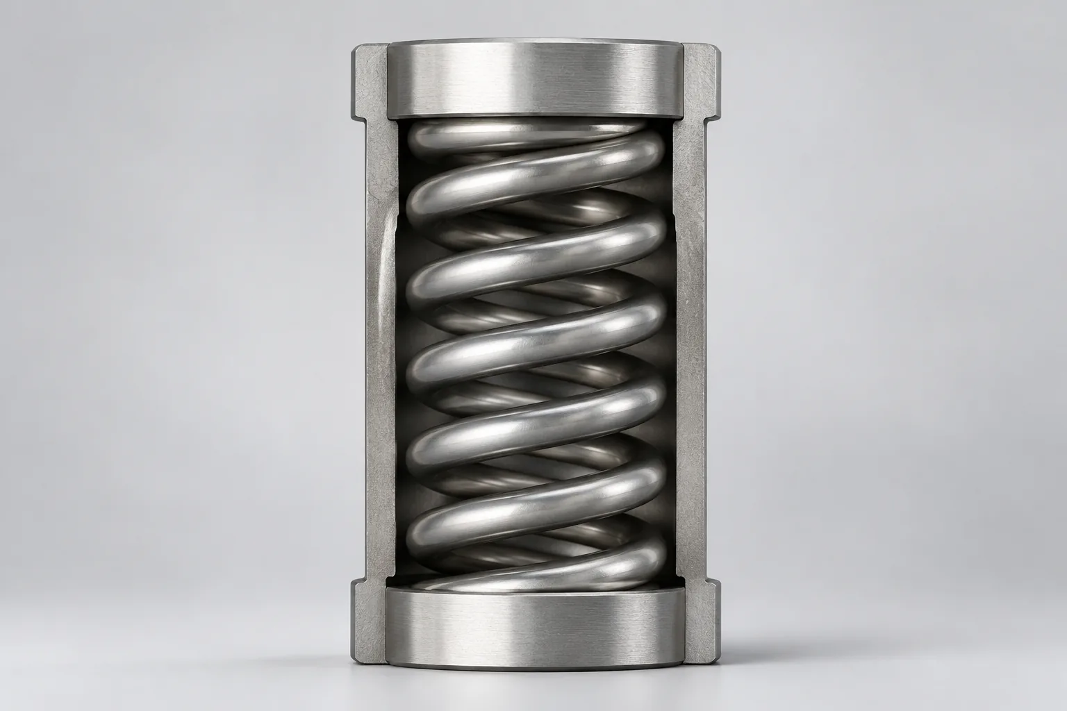
Typical applications include suspension, valves, switches, mechanisms, and vibration isolation. Design considerations include buckling, solid height, spring rate, and end conditions. Long slender springs may require guidance to prevent buckling. They are not ideal for applications requiring tension or torque without an additional mechanism.
Extension or Tension Springs
An extension spring is a helical coil that resists axial pulling force and often includes hooks or loops. Key parameters include initial tension, hook stress, body length, and maximum extension. Advantages include compact pull-force generation and simple attachment. Limitations include hook fatigue and stress concentration.
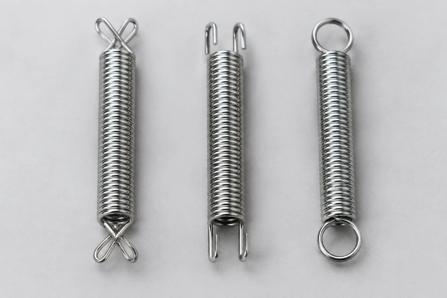
Typical applications include return mechanisms, tensioning devices, hardware, and reels. Hook or loop geometry must be designed for the load and fatigue requirements. Initial tension may not suit all return-force requirements, so check the force at the start of extension, not only at the end.
Torsion Springs
A torsion spring is a helical spring loaded in torsion; its legs transmit torque. Leg configuration, coil diameter, body length, and winding direction matter. Advantages include torque generation in a compact rotary package. Limitations include leg stress, friction, and mandrel clearance.
Typical applications include hinges, clamps, ratchets, and counterbalance mechanisms. Deflection direction and winding direction must match the assembly. A torsion spring is not a drop-in replacement for a compression or extension spring without redesign of the mounting and load path.
Flat Springs and Leaf Springs
Flat springs are formed from strip material, while leaf springs use stacked or tapered plates. Advantages include bending force over relatively short travel, and leaf springs can support heavy loads. Limitations include bulk compared with coil springs and interleaf friction in leaf stacks.
Typical applications include vehicle suspension, clips, contacts, latches, and electrical connectors. Design considerations include stress distribution, fatigue, interleaf friction, and mounting. Leaf springs are bulky compared with coil springs, so check load and space together rather than treating them as interchangeable.
Disc or Belleville Springs
Disc springs are conical washer-like springs loaded axially. They provide high force in a small axial space and can be stacked in series or parallel for travel and load requirements. Limitations include sensitivity to misalignment and edge loading, plus friction in stacks.
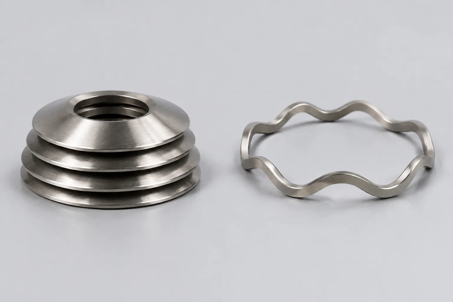
Typical applications include bolted joints, clutches, valves, preload, and overload protection. Design considerations include stack configuration, friction, nonlinear load-deflection behavior, and alignment. Stacking arrangement determines load and travel, so the stack drawing is part of the spring specification.
Conical and Volute Springs
Conical springs have a tapered coil diameter; volute springs use a tapered strip or coil form. Advantages include an increasing rate or a compact solid height, and volute forms are often used for heavy compression. Limitations include manufacturability and nonlinear behavior that is harder to model.
Typical applications include limited-space compression, shock absorption, and heavy machinery. Design considerations include manufacturability, nonlinear rate, and buckling. Confirm the force curve with the intended deflection range because the taper changes behavior as the spring compresses.
Spiral Springs and Clock Springs
A spiral spring is a flat strip wound into a spiral; it stores energy in bending or torsion. It is common in clockwork, retractors, and limited-angle rotary mechanisms. Advantages include compact energy storage in a rotary form. Limitations include end attachment and fatigue.
Design considerations include torque curve, strip material, end attachment, and fatigue. Typical applications include retractable cords, timers, reels, and spring motors. Torque ranges vary with size and material, so specify the required torque at the working angle.
Constant Force Springs
A constant force spring is a prestressed flat strip that delivers nearly constant force over extension. It is used where near-constant load is required over long travel. Advantages include stable force over a long stroke. Limitations include strip fatigue, attachment, and extension limit.
Typical applications include cable retractors, counterbalances, window regulators, and medical devices. Design considerations include strip fatigue, attachment, extension limit, and force tolerance. The mounting must allow the strip to unwind without rubbing or sharp bends.
Wave Springs
Wave-shaped wire or strip creates axial spring force in a compact height. Wave springs can replace disc springs or coil springs in tight axial spaces. Advantages include a low-profile axial force element. Limitations include sensitivity to wave count, flatness, and fatigue.
Typical applications include bearing preload, connectors, valves, and compact assemblies. Design considerations include wave count, load capacity, flatness, and fatigue. Bearing preload is a common use because the axial space is often limited, but the mating surfaces must be flat and aligned.
Gas Springs
A gas spring is a pneumatic or hydraulic-pneumatic device using compressed gas and a piston; it is not a wire spring. It provides controlled extension or compression force and often includes damping. Advantages include controlled motion and compact force assistance. Limitations include temperature and sealing sensitivity.
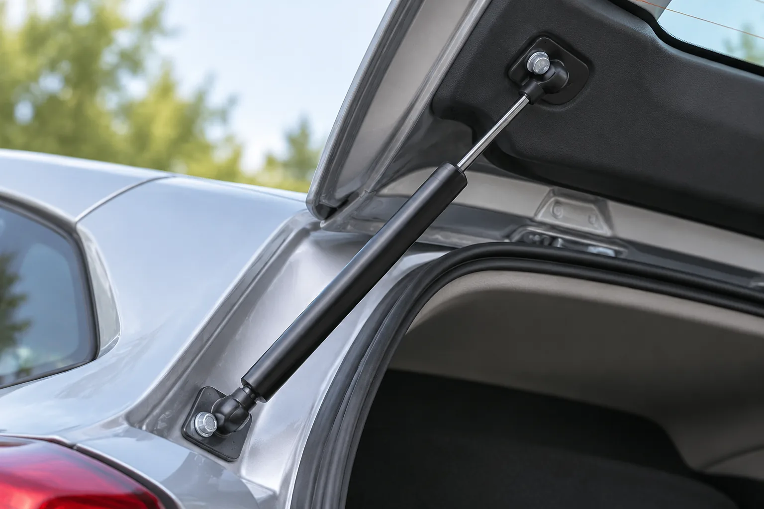
Typical applications include automotive hatches, furniture, medical beds, and machinery covers. Design considerations include temperature sensitivity, sealing, force curve, and mounting geometry. Force varies with temperature and orientation. A gas spring is not suitable as the only structural load-bearing member without secondary support.
Torsion Bars and Wire Forms
Torsion bars use twist along a straight bar, while wire forms are custom bent wire components. Torsion bars fit applications where a torsion spring may not, and wire forms combine spring and linkage or retention features. Limitations include end attachment and packaging for bars, and custom tooling and stress concentration for wire forms.
Typical applications include vehicle suspension, hinges, clips, retainers, and custom mechanisms. Design considerations include spline or end attachment, stress concentration, and custom tooling. Prototype wire forms early because bend radii and attachment points strongly affect fatigue.
Spring Materials and Surface Treatments
Material choice affects strength, fatigue, corrosion resistance, temperature capability, and magnetic properties. Common families include high-carbon or music wire, alloy steels, stainless steels, copper alloys, titanium, and nickel alloys. Surface treatments include plating, coating, shot peening, and passivation; these may affect fatigue and corrosion. The final choice depends on the service environment and load history.
Common Spring Materials
- Music wire or high-carbon steel: general-purpose material with good fatigue potential in appropriate environments.
- Oil-tempered and alloy steels: used for higher load or energy applications.
- Stainless steel: selected for corrosion resistance; magnetic response varies by grade.
- Copper alloys, titanium, and nickel alloys: specialty options for electrical, corrosion, temperature, or weight requirements.
These are starting points, not a final material selection. Grade, wire condition, heat treatment, and finish all affect the result.
Environment and Material Compatibility
Corrosion, temperature, humidity, chemicals, and abrasion influence material and coating selection. Consider galvanic compatibility and hydrogen embrittlement risk for high-strength steels. Food and medical applications may require specific material or finish documentation. Provide the service environment early so the material and finish are not chosen from load alone.
Key Design and Performance Parameters
Spring rate, load, deflection, stress, fatigue life, solid height, free length, and resonance drive comparison between spring types. These parameters are linked: a change in wire diameter, coil count, or stack height can shift rate, stress, and space at the same time. Numerical limits vary by design, so confirm them with the spring specification and applicable standard.
Spring Rate, Load, and Deflection
Spring rate relates force to deflection for linear springs; nonlinear springs have a changing rate. Load-deflection curves help compare compression, disc, wave, and constant-force springs. Application requirements determine allowable travel and force tolerance. Record the required force at specific positions, not just the maximum load.
Stress, Fatigue, and Cycle Life
Springs often fail by fatigue; stress range, surface condition, material, and environment matter. Shot peening and surface treatments can influence fatigue performance. Critical applications should validate cycle life through testing. A loss of force is a symptom, not a diagnosis, because permanent set, wear, and relaxation can produce similar results.
Space, Mounting, and Assembly
Available axial or radial space, mounting points, alignment, and assembly access affect type choice. Consider solid height, hook or leg geometry, bore clearance, and tolerances. Custom mounts may be needed for wire forms and torsion bars. Check the tolerance stack in the installed condition, because a spring that fits when free may bind when loaded.
How to Choose the Right Spring Type
Use a step-by-step selection framework: define function, load or motion, space, environment, life, standards, and cost. Compare candidate types with a decision matrix. Prototype and test before production release.
- Define the function and the force or motion required.
- Set the load, travel, cycle rate, and allowable envelope.
- Review the environment and material compatibility.
- Estimate life, maintenance access, and test needs.
- Compare candidate types and confirm the mounting concept.
Define Load, Motion, and Function
Specify force at positions, travel, cycle rate, and whether energy storage or isolation is required. Clarify whether linear or nonlinear force behavior is preferred. Include static versus dynamic loading. Also record overload, misalignment, and expected service life, because these conditions often decide the type more than the nominal load does.
Evaluate Space and Interface
Check axial height, diameter, mounting features, and adjustment needs. Consider assembly direction and tolerance stack-up. Confirm whether standard or custom geometry is required. A compact spring can save space but may concentrate stress or make inspection difficult.
Match Environment, Life, and Compliance
Review corrosion, temperature, cleanliness, and regulatory requirements. Estimate cycle life and maintenance access. Identify required test documentation. The inspection and documentation level should match the risk of the application, especially for safety-related or regulated products.
Applications of Springs by Industry
This section maps spring types to industry needs; the examples are illustrative, not exhaustive. Industry requirements vary, so verify standards and validation needs for the specific product.
Automotive and Transportation
Applications include suspension, brakes, clutches, pedals, seats, latches, and hatch supports. Common types include compression, extension, torsion, leaf, disc, and gas springs. Consider fatigue, corrosion, and safety requirements. Road exposure, vibration, and temperature cycles make material and finish selection part of the design.
Industrial Machinery and Automation
Applications include return mechanisms, tensioners, couplings, valves, conveyors, and vibration isolation. Common types include compression, extension, torsion, wave, disc, and constant-force springs. Consider duty cycle and maintainability. Access for inspection and replacement matters when equipment runs continuously.
Aerospace, Medical, Electronics, and Consumer Products
Aerospace applications emphasize weight, reliability, and qualification requirements. Medical applications may require cleanliness, precision, and biocompatibility where applicable. Electronics and consumer products use compact springs for contacts, battery compartments, retractors, and latches. Common types include torsion, compression, extension, constant-force, wire-form, and wave springs. Each sector adds its own documentation and validation expectations.
Comparison Table: Spring Types at a Glance
Use this table as a shortlist tool. The ratings are qualitative because allowable load, travel, and life depend on the actual design, material, and application.
| Spring type | Load type | Force behavior | Space or profile | Typical applications | Key limitations |
|---|---|---|---|---|---|
| Compression | Axial push | Linear or adjustable with geometry | Cylindrical or tapered coil | Suspension, valves, switches, mechanisms | Can buckle if slender; solid height limits travel |
| Extension | Axial pull | Linear, often with initial tension | Coil with hooks or loops | Return mechanisms, tensioners, reels | Hook stress and fatigue |
| Torsion | Torque or rotation | Angular rate | Coil with legs | Hinges, clamps, ratchets | Leg and mandrel stress; direction matters |
| Flat and leaf | Bending | Linear or progressive | Strip or stacked plates | Suspension, clips, contacts, latches | Bulky; interleaf friction |
| Disc | Axial push | Nonlinear; stack dependent | Shallow washer stack | Bolted joints, clutches, preload | Alignment sensitive; stack friction |
| Conical and volute | Axial push | Increasing rate possible | Tapered coil or strip | Limited-space compression, shock absorption | Manufacturability; nonlinear design |
| Spiral and clock | Bending or torsion | Torque curve | Flat spiral | Retractors, timers, reels | End attachment and fatigue |
| Constant force | Bending | Near constant over travel | Prestressed flat strip | Cable retractors, counterbalances | Extension limit and strip fatigue |
| Wave | Axial push | Linear or tailored | Wave-shaped wire or strip | Bearing preload, connectors, valves | Wave count and flatness sensitivity |
| Gas | Axial push or pull | Controlled, often damped | Cylinder and piston | Hatches, furniture, medical beds | Temperature and sealing sensitivity |
| Torsion bar | Torsion | Angular rate | Straight bar with end splines | Suspension, hinges | End attachment and packaging |
| Wire form | Combined | Custom | Bent wire | Clips, retainers, custom mechanisms | Custom tooling and stress concentration |
Common Failure Modes and Design Checks
Failure modes include fatigue fracture, corrosion, buckling, solid-height collision, excessive stress, relaxation, and wear. Design checks include stress analysis, clearance, guidance, material compatibility, and life testing. Failure consequences may require redundancy or inspection.
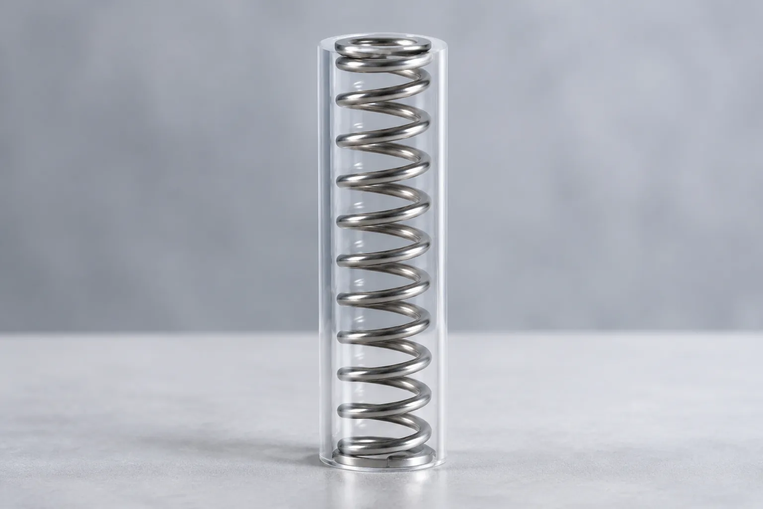
- Fatigue fracture: cracks can start at stress concentrations, corrosion pits, or surface damage.
- Buckling: long slender compression springs can bend sideways without guidance.
- Solid-height collision: coils or elements can contact before the intended travel is reached.
- Relaxation and permanent set: load or free length can change after sustained stress or temperature exposure.
- Wear and corrosion: rubbing, moisture, and chemicals can reduce section or initiate cracks.
A broken spring can be a symptom of misalignment, overload, or an incorrect material, not just a material fault. Review the installed load path and the service environment before changing the design.
Standards, Testing, and Quality Control
ISO 26909:2009 provides terminology for metal springs. ISO/TC 227 covers tolerances, terminology, and test methods for metal springs. ISO 22705-1 and ISO 22705-2 address measurement and test parameters for cold-formed compression springs and extension springs, respectively, both excluding dynamic testing. ISO 11891 addresses material, geometry, spring characteristics, tolerances, manufacturing, and test methods for hot-formed helical compression springs. Other standards address leaf-spring test methods and disc-spring practice. Exact standard selection depends on spring family, application, and market.
Typical checks include dimensions, load at deflection, rate, fatigue, surface finish, and material certificates. Inspection level should match application risk. For critical parts, define the test method, sampling, acceptance criteria, and documentation before production.
Conclusion
Types of springs and their applications are easier to compare when the decision starts with function, load direction, travel, space, environment, and cycle life rather than shape. Compression, extension, torsion, flat and leaf, disc, conical, spiral, constant-force, wave, gas, torsion-bar, and wire-form springs each solve a different combination of force and packaging needs. Use the comparison table as a shortlist, then check stress, fatigue, mounting, material compatibility, and applicable standards. Prototype and test the chosen design before production release, and confirm final values against the application specification.
FAQs
Q1: What are the main types of springs?
A: The main types include compression, extension or tension, torsion, flat and leaf, disc or Belleville, conical and volute, spiral and clock, constant-force, wave, gas, torsion-bar, and wire-form springs. They differ in load direction, force behavior, space envelope, and mounting, so the list is a starting point for selection rather than a complete design method.
Q2: How do I choose between a compression spring and an extension spring?
A: Choose a compression spring when the load pushes the spring shorter and the assembly can guide or contain the coil. Choose an extension spring when the load pulls the ends apart and hooks or loops fit the attachment points. Check buckling, solid height, initial tension, hook stress, and maximum extension before release.
Q3: When should I use a disc spring or a wave spring?
A: Use a disc spring when high axial force is needed in a shallow space and a stack can be tuned for load and travel. Use a wave spring when axial space is tight and a lower-profile force element is needed, such as bearing preload or a compact connector. Both are sensitive to alignment, flatness, friction, and stack or wave configuration.
Q4: What causes a spring to lose force?
A: Loss of force can come from permanent set, fatigue, creep or relaxation, wear, corrosion, or overheating. Compare free length and force output with the specification, inspect for cracks and wear, and check the operating load and temperature. A force loss is a symptom, so confirm the cause before changing material or design.
Q5: Do spring materials and finishes affect fatigue and corrosion?
A: Yes. Material grade, surface condition, residual stress, and coating or plating can change fatigue performance and corrosion resistance. Shot peening can introduce compressive residual stress, while some finishes may need careful control for high-strength steels. Specify the environment and verify the finish with the spring supplier.
Q6: Are gas springs the same as wire springs?
A: No. A gas spring uses compressed gas and a piston to produce a controlled force and often includes damping, while a wire spring relies on elastic deflection of metal. Gas spring force can vary with temperature and orientation, and the unit should not serve as the only structural support without a secondary member.
Q7: What should be checked before releasing a spring design?
A: Check load at defined positions, rate, travel, solid height or maximum extension, stress range, fatigue life, mounting alignment, material compatibility, and applicable standards. Confirm the finish and inspection documentation for the service environment. Prototype or test critical designs before production release, because a spring that fits the space can still fail through fatigue or resonance.