Quick Answer: Gears work by meshing teeth that carry rotary motion from a driver gear to a driven gear. A smaller driver turning a larger driven gear lowers output speed and raises torque; a larger driver turning a smaller driven gear does the opposite. In an ideal pair, power stays the same while speed and torque trade off. Real drives also depend on backlash, lubrication, alignment, bearing support, and losses.
To understand how gears work, it helps to separate the ideal relationship from the hardware that carries it. The ideal model explains why tooth count changes speed, why torque moves in the opposite direction, and why power links the two. The hardware model explains why a drive can still run hot, noisy, or short-lived when the ratio is correct.
What a Gear Does in a Mechanical Drive
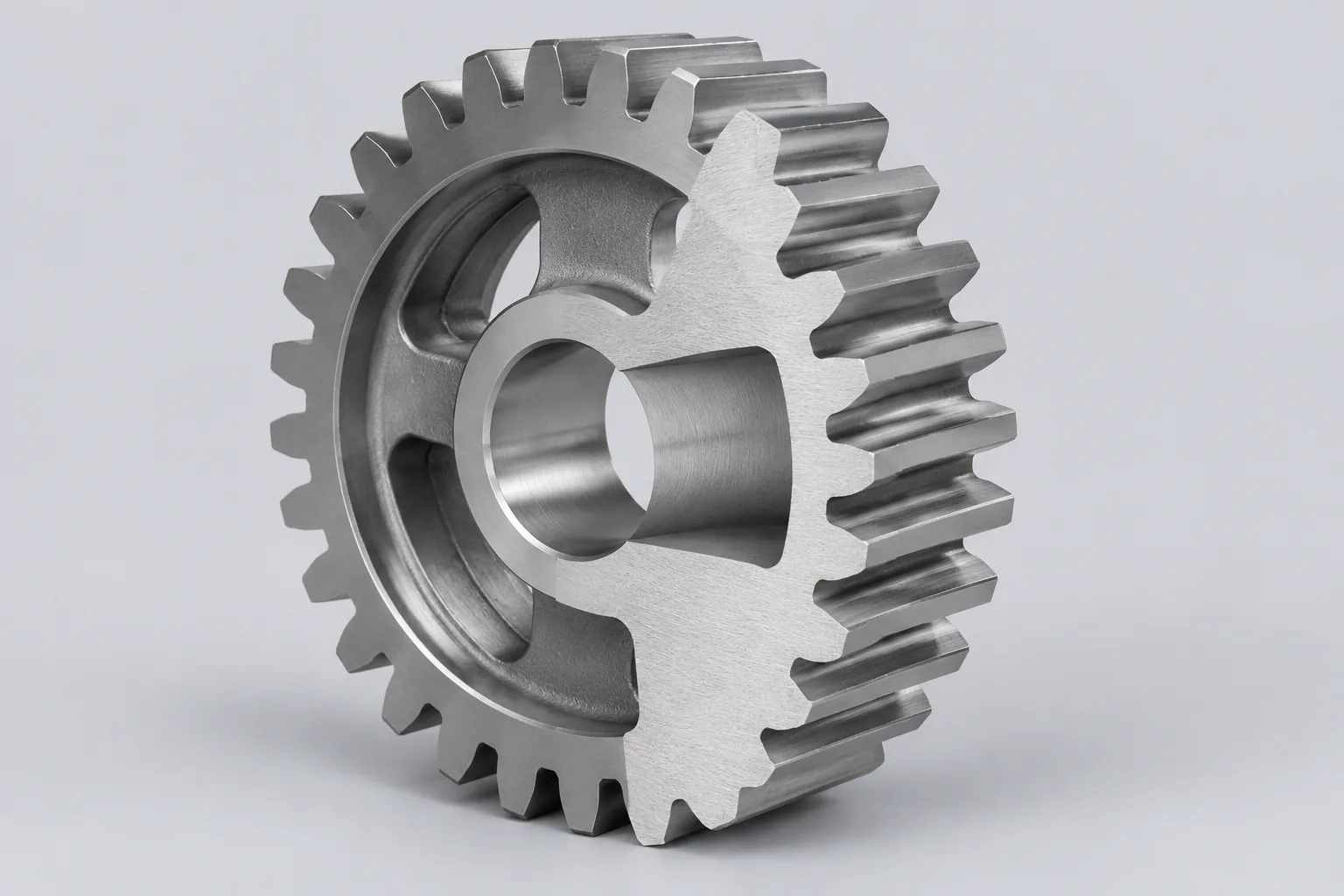
A gear is a toothed rotating component that transmits motion to another gear or to a rack. In a simple pair, the driver gear is the input, the driven gear is the output, and each gear is carried on a shaft. Bearings locate those shafts and keep the teeth in a workable mesh.
Gears do not create energy. They change speed, torque, direction, or the type of motion. A pair can slow an input and raise torque, speed up an input and lower torque, or reverse rotation; a rack converts rotation into linear movement.
The clean explanation assumes ideal rolling of the pitch circles and no losses in the mesh. That model is useful for ratio calculations, but it is only the starting point for a real drive.
Core Gear Terms Needed to Follow the Explanation
These terms are enough to follow the rest of the explanation. Exact definitions, symbols, and tolerance values should come from the applicable gear standard and the gear manufacturer’s design data.
- Tooth count: the number of teeth on a gear; it is the main input to the ratio between two gears.
- Pitch circle and pitch diameter: the reference circle used to describe gear size, with the pitch diameter being the diameter of that circle.
- Module or diametral pitch: a measure of tooth size; module is the metric form and diametral pitch is the inch-based counterpart.
- Pressure angle: the angle that defines the tooth flank form and the direction in which load is carried through the mesh.
- Center distance: the distance between the two shaft centers; it depends on the pitch diameters and the tooth counts.
- Gear ratio: the relationship between tooth counts and rotational speeds; it can be written as a speed ratio or a tooth ratio, so the direction must be stated clearly.
- Backlash: the running clearance between mating teeth. It is necessary to avoid binding and to allow lubrication and thermal expansion, not a performance feature by itself.
How Gears Work: Motion Transfer Through Meshing Teeth
As the driver turns, its teeth push the teeth of the driven gear. In an involute pair, contact moves along the line of action, so the driven gear rotates smoothly and continuously rather than through a series of collisions. The contact combines rolling and sliding. This explanation assumes continuous tooth contact and ideal rolling of the pitch circles.
An external gear pair reverses rotation direction: if the driver turns clockwise, the driven gear turns counterclockwise. An internal gear pair can rotate the output in the same direction. An idler gear placed between them reverses direction again and can bridge a distance, but by itself it does not change the overall ratio between the first driver and the final driven gear.
Gear type decides how motion is routed. Parallel-shaft gears keep the shafts side by side; bevel gears turn a corner; worm gears cross axes; rack-and-pinion converts rotation into straight-line movement. Crossed-axis designs need their own motion description because the contact geometry differs from a simple parallel pair.
Speed Relationship: Why Tooth Count Changes RPM
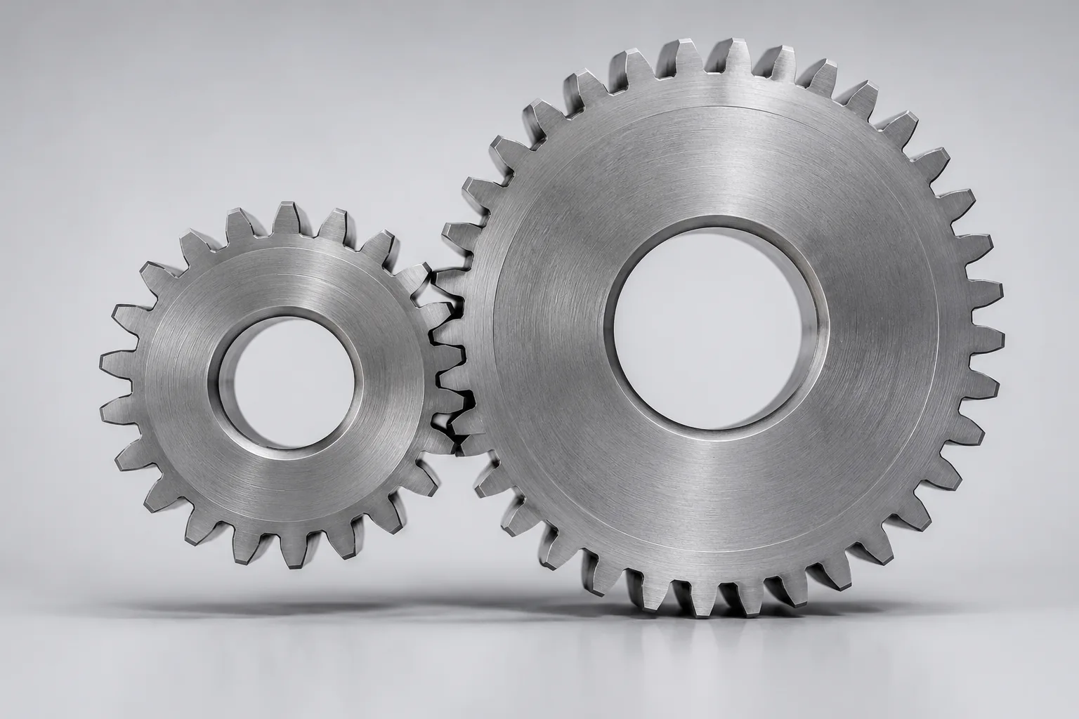
Speed follows tooth count. If a 20-tooth driver turns a 40-tooth driven gear, the driven gear turns at half the driver speed. The relationship for an ideal pair is rpm driven / rpm driver = teeth driver / teeth driven. The same ratio can be inverted depending on whether it is written as a speed ratio or a tooth ratio, so label the direction clearly.
Two practical cases are easy to check:
- A smaller driver and a larger driven gear produce a slower output speed.
- A larger driver and a smaller driven gear produce a faster output speed.
The relative tooth counts matter, not the overall size of the assembly by itself. A large gear with many teeth can be paired with a small pinion, and the ratio depends on the two tooth counts. Compound trains repeat the effect: each stage multiplies the ratio, which is why multi-stage gearboxes can produce large speed changes. The formula assumes ideal rolling of the pitch circles and neglects tooth deflection and losses.
Torque Relationship: The Speed-Torque Tradeoff
Torque moves in the opposite direction from speed. In an ideal pair, when the driven gear turns more slowly, it delivers more torque; when it turns faster, it delivers less. For the same ideal pair, T driven / T driver = teeth driven / teeth driver, which is the inverse of the speed relationship.
Power links the two: power = torque x angular velocity. A passive gearbox cannot create power. It can only trade speed for torque, or torque for speed, while losses reduce what comes out. Real losses mean the output torque is lower than the ideal calculation, or the input torque must be higher to hold the same output.
Efficiency losses, inertia, shock loads, and structural limits change real torque capacity. A ratio that looks acceptable on paper does not prove that the teeth, shafts, bearings, housing, and lubrication can carry the load.
Putting Speed, Torque, and Power Together
Start with input speed and input torque. The gear ratio sets output speed; the inverse ratio sets ideal output torque. In a passive system, output power cannot exceed input power. That is the accounting rule that keeps the speed-torque tradeoff honest.
Efficiency is the correction between the ideal and the real result: output power = input power x efficiency after consistent units are used. If speed is in rpm, convert it to angular velocity before combining it with torque in a power equation. Do not mix horsepower, watts, newton-meters, and pound-feet without conversion.
A neutral worked example can use symbolic input values and the ratio relationships above; it should not be presented as a performance claim for a specific gearbox. Efficiency varies by gear type, lubrication, load, and manufacturing quality, so use the manufacturer’s data when a real selection depends on it.
Compound Gear Trains and Multi-Stage Drives
A compound train uses more than one gear pair. A shaft may carry a driven gear from one stage and a driver gear for the next, so the stages share shafts and add their ratios. The overall ratio is the product of the individual stage ratios.
Before multiplying, define each stage ratio the same way. If one stage is written as driven-to-driver and another as driver-to-driven, the product will be wrong. Intermediate gears can change direction and help with packaging, but an idler does not act as a torque multiplier by itself.
Each stage adds shaft load, bearing load, alignment requirements, and efficiency loss. A multi-stage train can achieve a large ratio in a compact package, but the support structure and lubrication have to carry the result.
How Gear Type Affects Motion, Speed, and Torque
Gear type changes how the teeth meet, so it changes the hardware requirements around the same speed and torque relationships.
| Gear type | Shaft relationship | Motion result | Practical note |
|---|---|---|---|
| Spur | Parallel | Rotation in the opposite direction for an external pair | The simplest reference case, with straight teeth. |
| Helical | Parallel | Rotation in the opposite direction for an external pair | Gradual tooth engagement can run smoother and quieter than straight spur teeth under many conditions; thrust load needs support. |
| Bevel | Intersecting | Changes the axis of rotation | Used to turn a corner; tooth contact and setup are more demanding. |
| Worm | Nonparallel, commonly at a right angle | High reduction in a compact layout | May resist back-driving in some designs; confirm lead angle and friction for the specific unit. |
| Rack and pinion | Rotary to linear | Converts rotation into straight-line movement | Rack length sets the available stroke. |
Selection depends on load, speed, alignment, lubrication, and duty cycle. No single gear type is best on every dimension; comparative efficiency and load capacity have to come from the specific design data rather than a generic ranking.
Real-World Losses and Operating Limits
Real drives depart from the ideal model. Friction and sliding contact consume energy; backlash, misalignment, shaft deflection, and lubrication condition change contact and noise. None of these effects disappear because the ratio calculation is correct.
Bearings support the gear shafts and influence alignment, friction, noise, and load capacity. Heat, wear, and lubrication failure can limit torque capacity even when the speed-torque ratio looks acceptable. Gear strength and tooth loading must be checked separately from the ratio; a gearbox ratio does not prove tooth bending or surface durability.
High-shock, reversing, or high-speed applications may need additional dynamic and thermal analysis. Typical efficiency ranges and bearing load directions are application-specific, so use the design data for the actual drive rather than a generic table.
Common Misconceptions and Quick Checks
Several shortcuts cause bad decisions. Gears do not amplify power; they trade speed for torque or torque for speed. A larger gear is not automatically stronger or faster, because tooth count, material, tooth form, and load all matter. An idler gear changes direction and spacing, but it does not change the overall ratio between the input and output gears.
Before accepting a ratio calculation, confirm four things: the ratio direction is labeled consistently, the units are consistent, the efficiency assumption is stated, and the bearing and shaft support can carry the resulting loads.
Conclusion
How gears work comes down to a controlled exchange: meshing teeth transfer motion, tooth count sets speed, and torque changes in the opposite direction. In an ideal pair, power is the linking quantity; in a real drive, friction, backlash, lubrication, alignment, and bearing support decide what the hardware can actually deliver.
The safe next step is to check the complete drive, not only the ratio. Confirm tooth counts, ratio direction, unit consistency, efficiency assumptions, tooth and bearing loads, and the lubrication and alignment requirements for the application.
FAQs
Q1: Do gears increase torque?
A: In an ideal pair, torque increases when output speed decreases. A smaller driver turning a larger driven gear lowers speed and raises torque; real losses reduce the gain.
Q2: Does a bigger gear turn faster or slower?
A: A larger driven gear turns slower than a smaller driver gear when it has more teeth. Size alone is not the rule; compare tooth counts and the driver-to-driven arrangement.
Q3: What does an idler gear do to speed and torque?
A: An idler changes rotation direction and can bridge distance. By itself, it does not change the overall ratio between input and output, but it does add a shaft, bearing load, and efficiency loss.
Q4: Do gears change rotation direction?
A: External gear pairs reverse direction. Internal pairs can rotate the output the same way, and an idler adds another reversal.