Quick Answer
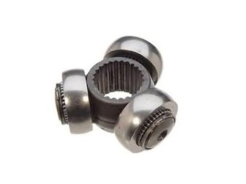
A tripod CV joint—also called a tripot joint or plunging CV joint—is a constant-velocity coupling that uses three needle-bearing rollers mounted on a three-arm spider (trunnion) running inside a three-grooved tulip housing. It transmits torque at constant speed while allowing up to 50 mm of axial plunge and up to 23°–26° of articulation. You will find it on the inboard (differential) end of most front-wheel-drive halfshafts—from Honda Civics to Volkswagen Golfs—where it absorbs the length changes that occur as the suspension moves up and down.
If your front-wheel-drive car shudders under hard acceleration or vibrates at low speeds, the tripod CV joint on the inner end of your halfshaft might be telling you something. While the outboard Rzeppa joint handles steering angles up to 47°, the inboard tripod joint has a different job: it must plunge in and out as the suspension compresses and rebounds, all while transmitting engine torque smoothly to the wheels.
But what exactly makes a tripod joint different from a Rzeppa joint? Why do almost all front-wheel-drive cars use tripod joints on the inner axle positions? And why does a torn boot on the inner joint cause a very different set of symptoms than a worn outer joint?
This article breaks down the tripod CV joint—how it works, what is inside it, the key variants you will encounter, where it is used, how it compares to the Rzeppa joint, what goes into its manufacturing, and what to look for when it starts to fail.
How Does a Tripod CV Joint Actually Work?
A tripod joint is a true constant-velocity (CV) joThemes 0int—the output shaft rotates at the same speed as the input shaft, regardless of the operating angle. But unlike a Rzeppa joint, which uses six steel balls and a cage, the tripod joint achieves constant velocity with a completely different mechanism.
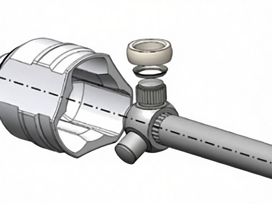
The joint consists of two main assemblies:
- A tripod spider (trunnion) with three arms spaced 120° apart, pressed onto the end of the halfshaft
- A tulip housing—a cup-shaped component with three matching tracks, splined to the differential output
Each arm of the spider carries a needle roller bearing capped by a spherical or barrel-shaped roller. These three rollers ride inside the three tracks machined into the tulip housing.
Here is how torque flows through the joint:
- The differential spins the tulip housing.
- The tracks in the tulip push on the rollers.
- The rollers push on the trunnion arms of the spider.
- Torque flows down the halfshaft to the wheel.
Because the rollers can slide along the tracks, the shaft is free to plunge in and out as the suspension cycles. This axial movement—typically 25–50 mm depending on the application—absorbs the length change that occurs when the lower control arm swings through its arc. The trunnion-and-tulip geometry delivers near-constant velocity output up to about 18°–23° of articulation, well beyond the 6°–10° the inboard end typically sees in normal service.
Above roughly 25°, the joint starts to bind, generate heat, and shed grease past the boot clamps.
Major Tripod Variants: GI, AAR, FTJ, and More
While the basic tripod design is universal, the industry has developed several distinct variants—each with specific performance characteristics and applications.
GI Joint (Standard Tripod)
The GI joint is the most common standard tripod design, offered by suppliers like GKN. It features a maximum articulation angle of 23° and plunge travel up to 50 mm. This design has been the industry standard for inboard applications on most front-wheel-drive vehicles since the 1970s. The GI joint delivers reliable performance at moderate cost and is used across Honda Civic, Toyota Corolla, and Volkswagen Golf applications.
AAR Joint (Advanced Tripod)
The AAR (Advanced Articulating and Plunging) joint is a premium evolution of the tripod design. Key improvements include:
- Maximum articulation increased to 26°
- Same 50 mm plunge travel as the GI design
- Lower axial resistance—the rollers are not fixed, allowing them to move freely
- Superior NVH (Noise, Vibration, Harshness) performance
The AAR joint is often specified for premium vehicles and applications where cabin comfort is a priority.
FTJ (Free-Ring Tripod Joint) / SFJ (Shudder-Less Freering Tripod Joint)
The FTJ is a further refinement that reduces roller sliding resistance by adding a free ring between the outer ring and the roller. However, this lower sliding resistance comes with a trade-off: at idle in Drive, it can transmit more engine vibration to the vehicle body. The SFJ variant is designed to mitigate this shudder issue. Unlike some other designs, the FTJ is typically serviceable—it can be disassembled for cleaning, inspection, and grease replacement.
Other Plunging Joint Types (for context)
Two other plunging CV joint designs are worth knowing for comparison:
- VL Joint (Ball Plunging) – a ball-type plunging joint with 22° articulation and 50 mm plunge travel
- DO Joint (Double Offset Joint) – a ball-type plunging joint with 26°–31° articulation and 50 mm plunge travel
Terminology Note: Tripod vs. Tripoid
The terms “Tripod” and “Tripoid” are often used interchangeably in the automotive industry. Some sources use “Tripoid” to refer specifically to the GKN-designed variant with a distinctive outer ring geometry. For most practical purposes—sourcing, repair, and specification—they refer to the same family of three-arm plunging joints.
Main Components of a Tripod CV Joint
A tripod CV joint consists of six main components:
Tulip Housing (Outer Race / Cup)
A cup-shaped housing with three axial tracks (grooves) machined into its inner surface. The tulip is typically splined to the differential output shaft or integrated with a flange. It is usually made from case-hardened alloy steel and houses the spider assembly.
Spider (Trunnion / Tripod Member)
A three-arm spider pressed onto the end of the halfshaft. The spider replaces the inner race found in a Rzeppa joint. Each arm carries a needle roller bearing. The spider is typically made from steel with a carbon content of 0.23% to 0.44% and features an effective hardened layer depth to resist wear.
Three Rollers (Needle Bearing Rollers)
Each trunnion arm carries a needle roller bearing capped by a spherical or barrel-shaped roller. The needle bearings allow the rollers to rotate very freely. The rollers ride inside the tulip tracks and slide axially to provide plunge travel. Rollers are mounted at 120° to one another.
CV Boot
A corrugated neoprene or thermoplastic cover secured by two clamps. The boot keeps grease in and contaminants out. Boots should be inspected at every routine service—roughly every 10,000–15,000 km (6,000–9,300 miles)—for cracks, splits, or loose clamps. Boot life varies with heat, age, and road conditions; many last 5–10 years.
Why Grease Selection Matters for Tripod Joints
Tripod joints require a specific lubricant formulation that is distinctly different from what Rzeppa joints use:
- Viscosity: Low-viscosity grease (typically NLGI 1 grade), not the heavier NLGI 1.5–2.0 grade used in Rzeppa joints
- Additives: No solid additives—molybdenum disulfide (MoS₂) or graphite are deliberately omitted from tripod grease. The GI and AAR bearings do not contain molybdenum in the grease.
- Penetration: Requires excellent penetration characteristics to flow into the tight clearances between the needle bearings and the trunnion
- Why this matters: The tripod’s needle bearings are more delicate than a Rzeppa’s ball-and-race interface. The trunnion steel is comparatively softer. The system lacks the “mass” to tolerate poor lubrication. Using Rzeppa grease in a tripod joint—especially the thicker, moly-loaded formulation—can cause binding, increased friction, accelerated needle bearing wear, and premature failure.
Always use the grease specified by the joint manufacturer. For most tripod applications, this is a moly-free NLGI 1 CV grease.
Retaining Hardware
Circlips, snap rings, thrust rings, and dished washers that secure the spider on the shaft and retain the assembly within the tulip housing.
How Tripod Joints Are Manufactured
For a tripod joint to survive the torque loads and plunge cycles of daily driving, its manufacturing process must meet tight tolerances.
Materials
Tripod joint components are typically manufactured from high-carbon, chromium-containing alloy steels:
- Rollers and trunnion components – 52100 (GCr15) bearing steel
- Tripod member (spider) – steel with 0.23%–0.44% carbon content, with an effective hardened layer
- Tulip housing – case-hardened alloy steel
Heat Treatment and Hardness
Finished tripod joint parts are hardened to Rockwell C 60–65 for superior crush strength and high ductility. Parts are then polished to a high surface finish to reduce friction and wear.
Manufacturing Tolerances
Tolerances are typically tight—±0.0001 inches for diameters and widths—because a set of rollers must fit precisely into the tulip tracks, and the assembly must operate with no play while providing smooth operation. Typical production sizes range from 1 inch to 4 inches in outer diameter.
Manufacturing Process
The typical production workflow for tripod joint components involves:
- Blank cutting – from 52100 (GCr15) high-carbon alloy steel tube
- Grinding – to specified outer diameter, inner diameter, and width
- Heat treatment – hardening to Rockwell C 60–65
- Polishing – to a high surface finish
- 100% dimensional inspection – verifying tolerances and fit
Cold and warm forging processes are also used for fabricating tripod housings.
Where Tripod CV Joints Are Used
The tripod CV joint is the most commonly used plunging-type CV joint in automotive driveshafts. Here is where you will find it:
Front-Wheel-Drive Passenger Cars
The tripod joint is used as the inboard (differential-side) joint on virtually every transverse-engine front-wheel-drive car built since the 1970s. Examples include GKN GI-series joints on Honda Civics and Volkswagen Golfs. Tripod-style joints have been used as inner joints on most domestic and Asian FWD models from 1983 to present. The tripod is well-suited to the limited operating angles of the inboard joint location—typically 6°–10° in normal service.
Four-Wheel-Drive and All-Wheel-Drive Vehicles
Tripod joints are used on the inboard positions of independent front suspension 4×4 and AWD vehicles.
Automatic Transmission Vehicles
Tripod CV joints have been especially favored for automatic transmission vehicles due to their noise and vibration advantages.
Electric Vehicles
In high-speed, high-torque EV applications, the tripod’s lower friction and heat generation make it increasingly attractive for inboard positions.
Layout Note
The tripod joint is almost always located on the inboard (differential) side, where it absorbs axial plunge from suspension travel. The outboard (wheel) side uses a Rzeppa joint to handle the large steering angles up to 47°. On some import applications, tripod joints may also be used as outer joints.
Tripod vs. Rzeppa vs. Cardan: Which One Do You Need?
The table below compares the tripod joint against its two primary alternatives, highlighting why each type is suited to different positions within the driveline:
| Feature | Tripod CV Joint | Rzeppa CV Joint | Cardan (U‑Joint) |
|---|---|---|---|
| Max articulation | 23°–26° continuous | 47°–52° continuous | ~30° practical |
| Speed uniformity | True CV (0% ripple) | True CV (0% ripple) | 2× ripple/rev |
| Axial plunge | Up to 50 mm | None (fixed type; plunging variants exist) | None |
| Torque capacity per diameter | Higher than Rzeppa (same size) | High | Highest |
| Friction & heat generation | Lower (needle bearings reduce scrub) | Higher (6 balls rolling/sliding) | Moderate |
| Typical location | Inboard (differential side) | Outboard (wheel side) | Rear driveshaft |
| Cost | Medium | Medium–high | Low |
| FWD service life | 150,000–250,000 km | 150,000–300,000 km | N/A |
Three critical takeaways from this table:
1. Tripod is stronger for its size. A tripod joint of the same outer diameter as a Rzeppa joint is typically stronger, which means it can be made smaller and lighter while still providing adequate strength.
2. Tripod generates less friction and heat. The needle-bearing roller design produces less sliding friction than the six-ball Rzeppa geometry. This lower friction is a significant advantage in high-speed, high-torque EV applications.
3. Tripod cannot match Rzeppa on articulation. The tripod’s maximum articulation is limited to 23°–26°, compared to 47° for a standard Rzeppa. That is why the tripod stays on the inboard side, where angles rarely exceed 10°.
So the choice is not about which is “better” overall—it is about which constraint drives your design: axial plunge + lower friction (choose Tripod) or articulation angle (choose Rzeppa).
NVH and Generated Axial Force: What Engineers Need to Know
The tripod joint’s design has significant implications for vehicle Noise, Vibration, and Harshness (NVH) performance—a key consideration for engineers specifying driveline components.
Generated Axial Force (GAF)
As torque flows through a tripod joint, internal friction creates an axial thrust along the shaft—this is known as the Generated Axial Force (GAF). The magnitude of this force is influenced by lubricant condition, torque load, operating speed, articulation angle, and the specific joint design. AAR designs typically produce lower GAF than GI designs, which contributes to their superior NVH characteristics.
Low Sliding Resistance vs. NVH Trade-off
The FTJ (Free-Ring Tripod Joint) design achieves very low sliding resistance, which reduces friction and heat. However, this low resistance can become a liability in certain conditions: when the vehicle is stationary in Drive with the engine idling, the low internal friction may transmit more engine vibration into the vehicle body. This is why some manufacturers introduced the SFJ (Shudder-Less Freering Tripod Joint)—to retain the friction benefits while damping the vibration transmission.
Plunge Resistance and NVH
The GI-type tripod joint offers low plunge resistance, which contributes to good NVH performance. Higher plunge resistance would transmit suspension-induced forces back through the driveline, creating boom and vibration in the cabin. This is one reason tripod joints are preferred over some ball-type plunging designs for inboard applications.
Real-world implication: When specifying or selecting a tripod joint, the engineer must balance the need for low friction (efficiency) against the risk of vibration transmission (NVH). The AAR and SFJ variants are designed precisely to achieve this balance.
Common Failure Modes and How to Diagnose Them
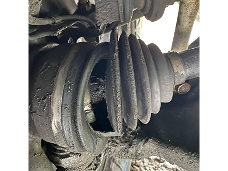
Common Causes of Failure
Torn Boot (The #1 Cause)
A damaged boot—torn, cracked, or with a loose clamp—is the most common reason tripod joints wear out prematurely. Once the boot fails, grease escapes and water, road salt, and grit enter the joint. The abrasive particles accelerate wear on the rollers, tracks, and needle bearings.
Needle Bearing Collapse
When lubricant breaks down or is washed out due to a torn boot, the needle bearings inside the tripod rollers can collapse. This causes major vibration, most noticeable upon acceleration.
Track Wear (Flats on Tulip Tracks)
Over time, the trunnion arms can wear flats into the tulip tracks. When this happens, the rollers shock-load into those flats every time torque reverses—producing a clunk on hard acceleration from a stop.
Roller-Needle Galling
A rhythmic shudder during steady acceleration in a turn points to roller-needle galling, which seizes the roller on the trunnion. This is a more advanced failure mode that typically follows prolonged contamination or lubrication failure.
Contamination
Once the boot fails, contaminants accelerate wear on the rollers, tracks, and needle bearings.
Wrong Grease
Using Rzeppa-style grease (thicker, molybdenum-loaded NLGI 1.5–2.0) in a tripod joint can cause binding, increased friction, accelerated needle bearing wear, and premature failure. Always use moly-free NLGI 1 CV grease specifically formulated for tripod joints.
Typical Symptoms
| Symptom | What It Means |
|---|---|
| Shudder or vibration under acceleration | Classic inner tripod joint wear. Most noticeable at low speeds (0–40 km/h). Often caused by needle bearing collapse or sticking spider assembly. |
| Clunk on hard acceleration from a stop | Trunnion arms have worn flats into tulip tracks—rollers shock-load into those flats every time torque reverses. |
| Rhythmic shudder during acceleration in a turn | Roller-needle galling—the roller seizes on the trunnion. |
| Grease splatter | Torn inner boot. Grease flung around the inner wheel well, control arm, or underbody. |
Diagnosis and Repair
Inner vs. Outer joint symptoms: A worn outboard Rzeppa joint makes its most noise while cornering (clicking on turns). A worn inboard tripod joint makes its most noise while accelerating and decelerating—shudder, vibration, or clunk under load.
Early detection: If you catch a torn boot before the joint starts making noise—and the joint has only been exposed for a few hundred kilometers—you can clean the joint, repack it with fresh CV grease, and replace the boot. This can save the joint.
Once it shudders or clunks: If the joint is already vibrating or clunking under acceleration, the internal components are damaged. Replacing just the boot will not fix it. The tripod bearing, spider, or entire halfshaft assembly needs replacement.
Inspection schedule: CV joints themselves do not have a fixed replacement interval. But the boots should be inspected at every routine service—roughly every 10,000–15,000 km (6,000–9,300 miles). Look for cracks, splits, loose clamps, or grease flung around the underbody.
Service life: With intact boots, tripod joints often exceed 150,000–250,000 km (93,000–155,000 miles). Boots are wear items and should be inspected every service.
Practical Repair Tips for Shops and DIYers
Beyond identifying the symptoms, here is what matters for repair decisions:
The Early Intervention Window
If a boot tear is discovered while the joint is still quiet and free of measurable play (no shudder, no clunk, smooth rotation), a boot-only repair is entirely viable. Clean the joint thoroughly, inspect the rollers and tracks for scoring, repack with fresh CV grease, and install a new boot. This can restore full service life at a fraction of the cost of a halfshaft replacement.
Inner Joint vs. Outer Joint Wear Patterns
The inner tripod joint and outer Rzeppa joint fail with different symptoms:
- Outer joint failure: Clicking or popping on turns—most noticeable at full steering lock
- Inner joint failure: Shudder or vibration under acceleration—especially at low speeds (0–40 km/h)
This distinction is critical for accurate diagnosis. If a customer reports a “clicking on turns,” the outer joint is the problem. If they report “shudder on take-off,” the inner tripod joint is the likely culprit.
The “Boot-Only” Trap
The clock starts ticking the moment the boot tears. If the vehicle continues to be driven for weeks or months, debris erodes the tracks and needle bearings. By the time the shudder starts, the damaged joint can also damage surrounding components—the wheel bearing, hub, or even the transmission output seal. A simple boot repair turns into a much larger repair bill.
Replacing Just the Tripod Bearing
In some cases, when the inner driver (tulip housing) is still in good condition, it is possible to replace just the tripod bearing (the spider and roller assembly) along with the axle shaft. The outer CV joint may still be fine if there was no clicking on turns. This approach can save cost compared to replacing the entire halfshaft assembly.
Repair Kits and Serviceability
Unlike the Rzeppa joint, the tripod joint is generally serviceable and repairable. While most OEMs specify replacement of the entire halfshaft assembly, the aftermarket offers separate tripod units for a wide range of vehicles—FEBEST, for example, catalogs dozens of tripod variants for Ford, Honda, Nissan, Toyota, Volkswagen, and Audi applications.
For certain transmissions—such as the Renault Logan and Lada Largus JH3 gearbox—the tripod is housed directly inside the transmission casing. In these cases, a complete inner CV joint repair kit is required (tripod + boot + clamps + seals + bearings). The OEM only sells the complete driveshaft, making the tripod repair option significantly more cost-effective.
Torque Capacity and Plunge Limits
The torque capacity of a tripod CV joint is determined by the tangential load on each of the three rollers, the effective pitch radius, and the number of rollers sharing the load.
The fundamental relationship is:
F_roller = T / (3 × r)
Where:
- F_roller = tangential load on each roller
- T = input torque
- r = effective pitch radius (torque arm from joint center to roller contact)
Torque is shared equally by the three trunnion rollers, which are spaced 120° apart. The tripod joint offers high plunge capacity and high torque capacity compared with ball-type joints. It also has good noise and vibration performance, offering lower plunging resistance than ball-type joints.
Plunge and Articulation Limits
Typical plunge travel is 25–50 mm depending on the application. A typical tripod CV joint has up to 50 mm of plunge travel and 23°–26° of angular articulation. Specific variants vary:
- Standard tripod joint (GKN GI-series): 23° maximum articulation, 50 mm plunge
- Premium AAR socket joint: Up to 26° articulation
- Some variants: 25 mm maximum plunge in each direction (at which it has no articulation)
Binding Region
Near-constant velocity behavior is assumed below about 23°; binding risk rises near 25°. Above roughly 25°, the joint starts to bind, generate heat, and shed grease past the boot clamps.
Generated Axial Force (GAF)
As detailed in the NVH section above, the tripod joint generates an axial force during power transmission. AAR-type tripod joints are specifically engineered to produce lower GAF than GI designs, contributing to their superior NVH performance.
Real-world example: A typical front-wheel-drive passenger car with 200 N·m of engine torque and a pitch radius of 25 mm would see a tangential roller load of approximately:
F_roller = 200 N·m / (3 × 0.025 m) = 2,667 N per roller
This load is well within the capacity of a properly designed tripod joint with hardened 52100 steel rollers and tracks.
Conclusion: Key Takeaways on Tripod CV Joints
The tripod CV joint is one of the most successful mechanical designs in modern automotive drivelines. Since it became the standard inboard joint on front-wheel-drive vehicles in the 1970s, it has enabled smooth, vibration-free power delivery while accommodating the constant length changes of suspension travel.
Here is what you need to remember:
- It is a true constant-velocity joint—no speed ripple, even at 23°–26° of articulation.
- Three needle-bearing rollers on a spider transmit torque while allowing up to 50 mm of axial plunge.
- Several variants exist—GI (standard, 23°), AAR (premium, 26°), and FTJ/SFJ (low friction, serviceable).
- Grease matters critically—tripod joints require low-viscosity, molybdenum-free NLGI 1 grease with excellent penetration, not Rzeppa-style grease.
- NVH is a design factor—GAF, plunge resistance, and the friction-vibration trade-off are key considerations in joint selection.
- The boot is everything—the #1 cause of failure is a torn boot allowing grease loss and contamination.
- Symptoms are different from outer joint failure—shudder or vibration under acceleration (not clicking on turns) points to the inner tripod joint.
- Tripod joints are repairable—unlike many Rzeppa designs, the tripod can often be rebuilt with a new spider, rollers, boot, and grease.
- Catch it early—replace the boot before the joint shudders, and you can save the joint.
- Once it shudders or clunks, it is too late—the joint is already damaged and needs replacement.
For manufacturers and suppliers in the driveline industry, understanding the tripod joint’s geometry, variants, materials, and failure modes is not just academic—it is the foundation for producing reliable, long-lasting CV components. Whether your role involves designing drivelines for next-generation EVs, repairing worn axles in the workshop, or sourcing components for manufacturing, a solid grasp of tripod joint fundamentals will serve you well.
FAQs About Tripod CV Joints
Q: What is a tripod CV joint?
A: A tripod CV joint—also called a tripot joint or plunging CV joint—is a constant-velocity coupling that uses three needle-bearing rollers on a three-arm spider running inside a three-grooved tulip housing. It transmits torque at constant speed while allowing up to 50 mm of axial plunge and 23°–26° of articulation. It is used as the inboard joint on most front-wheel-drive halfshafts.
Q: What is the maximum angle a tripod joint can handle?
A: Standard GI tripod joints handle up to 23° continuous. Premium AAR socket joint designs can reach 26°. Above roughly 25°, the joint starts to bind, generate heat, and shed grease.
Q: What is the difference between a GI joint and an AAR joint?
A: GI (standard) joints offer 23° articulation and are the most common design. AAR (Advanced Articulating and Plunging) joints offer 26° articulation with lower axial resistance and superior NVH performance—they are a premium variant used in vehicles where cabin comfort is a priority.
Q: What is an FTJ or SFJ tripod joint?
A: FTJ (Free-Ring Tripod Joint) features a free ring that reduces roller sliding resistance for lower friction. The SFJ (Shudder-Less Freering Tripod Joint) is a variant designed to mitigate the vibration transmission that can occur with low-resistance designs at idle. FTJ designs are typically serviceable.
Q: What is the difference between a tripod and a Rzeppa CV joint?
A: A tripod joint offers greater axial plunge (up to 50 mm) and lower friction, making it ideal for the inboard (differential) position. A Rzeppa joint offers greater articulation (47° vs. 23°–26°), making it ideal for the outboard (wheel) position where steering angles are large. A tripod joint of the same size is typically stronger.
Q: What grease should I use in a tripod CV joint?
A: Tripod joints require low-viscosity NLGI 1 CV grease with no molybdenum disulfide (MoS₂) or graphite additives. It must have excellent penetration to flow into the needle bearing clearances. Do not use Rzeppa-style grease (thicker, moly-loaded NLGI 1.5–2.0)—it will cause binding, increased wear, and premature failure.
Q: What are the symptoms of a failing tripod CV joint?
A: The classic symptom is shudder or vibration under acceleration—especially at low speeds (0–40 km/h). Other symptoms include a clunk on hard acceleration from a stop (worn flats in tulip tracks), rhythmic shudder during acceleration in a turn (roller-needle galling), and grease splatter from a torn boot.
Q: My inner boot is torn but the joint is not shuddering yet. What should I do?
A: If you catch it early—before the joint starts shuddering and within a few hundred kilometers of the tear—you can clean the joint, repack it with fresh NLGI 1 moly-free CV grease, and replace the boot. This can save the joint. If it is already shuddering or clunking under acceleration, the joint is damaged and must be replaced.
Q: Do tripod CV joints need regular maintenance?
A: The joint itself is sealed and maintenance-free. But the boots need regular visual inspection—every 10,000–15,000 km (6,000–9,300 miles) or at every routine service. Look for cracks, splits, loose clamps, or grease flung around the underbody.
Q: How long does a tripod CV joint last?
A: With intact boots, tripod joints typically exceed 150,000–250,000 km (93,000–155,000 miles). Boot life varies with heat, age, and road conditions; many last 5–10 years.
Q: Can I replace just the boot, or do I need to replace the whole joint?
A: You can replace just the boot—if the joint is not shuddering and has not been contaminated for long. If the joint is already shuddering or clunking under acceleration, the internal components are damaged and the joint or halfshaft assembly must be replaced.
Q: Why is the tripod joint used on the inside (differential side) and not the outside?
A: Because the inside joint needs to handle axial plunge—the length change that occurs as the suspension moves up and down. The tripod joint’s strength is axial plunge (up to 50 mm). The outside joint needs to handle large steering angles—up to 47°—which is the Rzeppa joint’s strength.
Q: Is a tripod joint repairable?
A: Yes. Unlike many Rzeppa designs, the tripod joint is generally serviceable and repairable. The spider (with rollers) can be replaced independently of the tulip housing. Complete repair kits—including the tripod bearing, boot, clamps, seals, and grease—are available for most common applications from aftermarket suppliers.
Q: How much does it cost to replace a tripod CV joint?
A: The cost varies widely by vehicle and whether you replace just the tripod bearing or the entire halfshaft. A boot-only repair is the most affordable option; replacing the entire halfshaft assembly is significantly more expensive. Labor costs also vary by region and shop rate. Many repair shops recommend replacing the entire halfshaft assembly because it saves labor time and includes a new outer joint as well, but for vehicles where the outer joint is still in good condition, replacing just the tripod bearing can be a cost-effective alternative.