Quick Answer
A tripod CV joint transmits engine torque at a constant rotational speed while allowing the drive shaft to change length as the suspension moves. Three needle-bearing rollers mounted on a central spider travel inside straight grooves machined into a cup-shaped housing. This design provides up to 23–26 degrees of articulation and 25–50 mm of plunge travel, ensuring smooth power delivery regardless of road conditions.
You press the accelerator. The engine delivers torque. The wheels turn. But how does power actually bend its way around corners and travel up and down over bumps—without breaking, binding, or vibrating?
The answer lies in a compact, clever component called the tripod CV joint. If you drive a front-wheel-drive car, you have two of these sitting at the inner ends of your drive shafts, right next to the differential. Despite being hidden inside rubber boots and packed in grease, their job is remarkably demanding: they must deliver full engine torque at a constant velocity while constantly stretching, compressing, and angling themselves.
To understand how they do this, we need to look inside—at the three legs, the needle bearings, and the straight grooves that make this joint so uniquely capable.
What Does the Tripod CV Joint Actually Do?
Before explaining the “how,” it is critical to understand the “what” and the “why.”
Constant Velocity — The Core Advantage
A traditional universal joint (U-joint) speeds up and slows down twice per revolution when operating at an angle. This creates vibration and wear. The tripod joint eliminates this problem entirely: the output shaft rotates at exactly the same speed as the input shaft, regardless of the working angle. This “constant velocity” (CV) property is what gives the joint its name and makes it indispensable in modern drivetrains.
Plunge — Accommodating Suspension Travel
As your car hits a bump, the wheel moves up. As it rolls over a dip, the wheel drops. This changes the distance between the transmission and the wheel hub. The tripod joint must lengthen and shorten to accommodate this movement. This axial sliding capability is known as “plunge.”
Because the inboard joint (differential side) experiences the greatest changes in shaft length, the tripod joint is almost always placed there. The outboard joint—typically a Rzeppa ball-type joint—handles the steering angles instead.
Inside the Joint: The Core Components
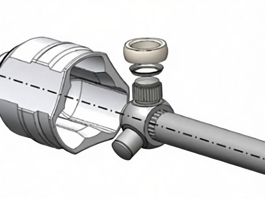
To understand the working principle, you must first visualize the three main mechanical parts that make up the assembly.
| Component | Description | Function |
|---|---|---|
| Outer Housing (Cup) | A cylindrical outer casing featuring three longitudinal raceways precision-ground into its interior bore. | Provides the rotational outer surface and guides the rollers linearly. |
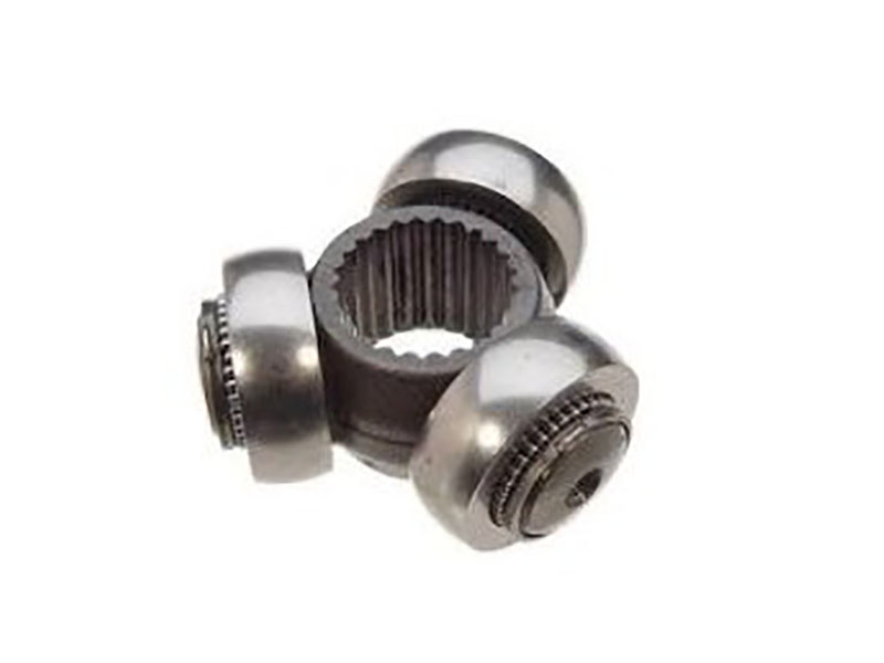
| Spider (Tripod) | A splined central body with three radially projecting pins spaced at 120° intervals. | Acts as the inner driving element, transferring torque from the input shaft to the rollers. |
| Rollers with Needle Bearings | Individual roller assemblies mounted on each pin, with needle bearing sets housed inside to enable free rotation. | Reduces friction by rolling against the housing walls instead of sliding. |
The housing connects to the output shaft (or flange), while the spider is splined to the input shaft.
Step-by-Step: The Working Principle
Here is the exact sequence of mechanical events that occurs when the tripod joint transmits power.
- Power Input — Torque enters the joint through the input shaft, which rotates the spider (tripod) around its central axis.
- Force Transmission to Rollers — As the spider rotates, the three pins push against their respective rollers. Because the pins are fixed to the spider, this rotational force is transferred directly to the rollers.
- Rolling Contact — Each roller’s internal needle bearing set permits rotation around its supporting pin. This rolling action—rather than sliding contact—dramatically reduces frictional losses and thermal buildup as the rollers traverse the housing raceways.
- Pushing the Housing — Each roller presses against the straight side walls of the outer housing’s tracks. This lateral force pushes the housing to rotate in the same direction as the spider.
- Constant Output — Because the tracks are straight (not curved), the rollers maintain a consistent radial distance from the center of rotation as they slide. This geometry ensures that for every degree the spider turns, the housing turns exactly one degree—delivering perfect constant velocity.
- Axial Plunge — Simultaneously, the rollers slide back and forth along the straight tracks within the housing. This axial movement compensates for the changing length of the drive shaft caused by suspension travel, without interrupting the rotational power flow.
Key Working Parameters and Limits
The “work” of this joint is defined by specific physical limits. Exceeding these limits causes binding, excessive heat, or failure.
- Maximum Articulation Angle — Typically 23 to 26 degrees. The inboard end of a drive shaft rarely sees more than 6–10 degrees in normal service, so this is more than sufficient. Above roughly 25 degrees, the joint starts to bind and generate excessive heat.
- Plunge Travel Range — 25 to 50 millimeters (approximately 1.0 to 2.0 inches), depending on the application. This is the total distance the rollers can slide forward or backward inside the grooves.
- Track Geometry — Maintaining the geometric integrity of these raceways is essential. Any degradation in track surface quality or straightness leads to unwanted oscillations and audible disturbances during operation.
The Role of the Needle Bearings
The needle bearings inside the rollers are the secret to the joint’s efficiency. They allow each roller to rotate on its pin, converting sliding friction into much lower rolling friction. This drastically reduces operating temperatures and allows the joint to handle high torque loads without seizing.
How It Compares to a Rzeppa (Ball-Type) Joint
Many people confuse the tripod joint with the Rzeppa (ball-type) CV joint. While both deliver constant velocity, their working mechanics and applications are distinct.
| Operational Aspect | Tripod Joint | Rzeppa Joint (Ball-Type) |
|---|---|---|
| Power Transmission | Uses 3 rollers on a spider. | Uses 6 steel balls in a cage. |
| Inner Race | Spider replaces the inner race. | Separate inner race with curved grooves. |
| Groove Shape | Straight tracks for axial sliding. | Curved tracks for ball guidance at angles. |
| Primary Working Motion | Rollers slide axially along the tracks. | Balls roll circumferentially in curved arcs. |
| Articulation Capability | Handles up to 23–26 degrees. | Handles up to 45–54 degrees. |
| Plunge Capability | High (25–50 mm). | Minimal (limited by ball travel). |
| Friction | Lower (needle bearings roll). | Higher (balls contact races). |
The Rzeppa design accommodates significantly greater angular misalignment—up to 45–54 degrees—making it the preferred choice for wheel-end (outboard) applications where steering geometry demands maximum articulation. Conversely, the tripod joint’s generous plunge capacity suits it for the inboard position where suspension travel creates the greatest axial length fluctuation.
What Happens During Operation That Can Affect Performance?
Understanding how the joint works also requires knowing what can work against it during real-world operation.
Generated Axial Force (GAF)
Under loaded rotation, frictional interactions between the rolling elements and their guide surfaces produce an axial thrust known as Generated Axial Force (GAF). This parasitic load acts along the shaft axis, tending to displace the spider assembly axially within the housing. GAF is a natural byproduct of the rolling and sliding contact mechanics and exhibits a third-order characteristic relative to driven shaft speed.
GAF has a direct negative impact on NVH (Noise, Vibration, and Harshness) characteristics. Higher GAF leads to more noticeable cabin vibrations. This issue is particularly prominent in electric vehicles, where the absence of engine noise makes drivetrain vibrations much more perceptible to occupants.
The Critical Role of Lubrication
The joint relies entirely on a thin film of specialized grease to maintain separation between the needle bearings and the pins, and between the rollers and the tracks. As the joint articulates and plunges, the grease is constantly churned and pushed into the contact zones. Without this lubricating film, friction rises exponentially, the “rolling” action ceases, and rapid metal-to-metal wear follows.
Boot Integrity
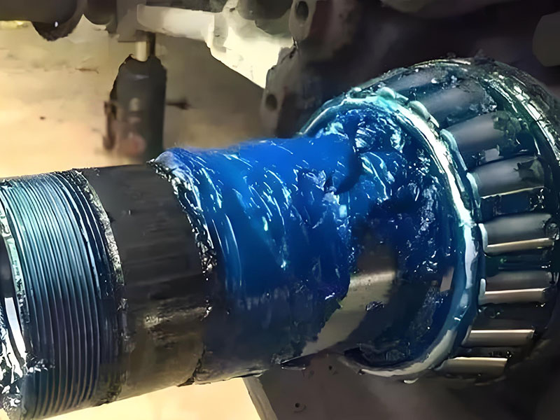
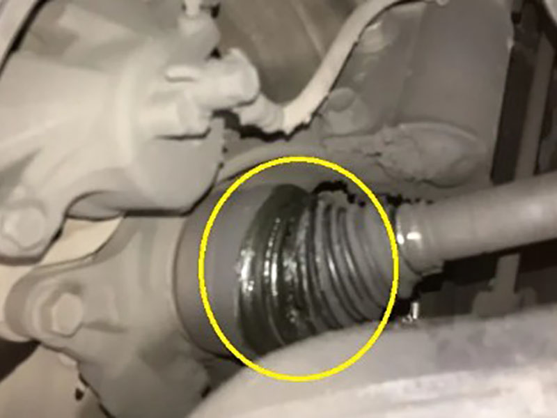
The protective elastomeric cover—commonly referred to as the CV boot—fulfills two essential functions: excluding external debris while retaining the joint’s specialized lubricant. Boot compromise through splitting or material fatigue allows lubricant escape and contaminant ingress, representing the most frequent failure mode observed in service.
Conclusion
The tripod CV joint works through a synchronized interaction of rotation and sliding. Three needle-bearing rollers, mounted on a central spider, travel along straight tracks inside a cup-shaped housing. This design accomplishes two critical tasks simultaneously: it transmits rotational power at a perfect 1:1 constant velocity, and it allows the drive shaft to change length by 25 to 50 mm to absorb suspension movement.
Unlike universal joints, it never causes speed fluctuations. Unlike ball-type CV joints, it excels at plunging. By maintaining up to 23–26 degrees of articulation and relying on the low friction of needle bearings, this joint ensures that power from your engine or motor reaches the wheels smoothly, regardless of the road conditions.
For anyone working on vehicle design or maintenance, the key takeaways are straightforward: respect the grease, protect the boot, and understand that this joint works hardest not when you’re driving straight, but when you’re accelerating out of a corner with the suspension fully compressed.
FAQs
Q: How does a tripod joint maintain constant velocity while sliding?
A: Plunge motion is directed axially—parallel to the shaft axis—rather than radially. Since the roller path follows linear raceways oriented along the shaft centerline, the effective radius from the rotation axis stays unchanged throughout the sliding range. This geometric property preserves the 1:1 angular velocity ratio regardless of plunge position.
Q: What is the maximum operating angle for a tripod CV joint?
A: Typically, a tripod CV joint operates efficiently up to 23 to 26 degrees of articulation. Above roughly 25 degrees, the joint starts to bind and generate excessive heat. In normal service, the inboard end of a drive shaft rarely sees more than 6–10 degrees.
Q: Why does the tripod joint use needle bearings instead of plain bushings?
A: Needle bearings significantly reduce friction by converting sliding contact into rolling contact. This allows the rollers to move smoothly along the tracks and rotate around the spider pins under heavy torque loads, generating less heat and less wear than a plain bushing would.
Q: How do the straight grooves allow the joint to articulate at an angle?
A: When the joint operates at an angle, the spider pins tilt relative to the housing tracks. The rollers compensate for this misalignment by tilt-walking—they roll slightly up and down the side walls of the tracks, allowing the three legs to find a neutral position that balances the forces. This process also generates the Generated Axial Force (GAF) discussed above.
Q: Does the tripod joint work the same way in an electric vehicle?
A: Yes, the mechanical working principle is identical in EVs. However, torque delivery is instant and the powertrain is much quieter, so the GAF vibration and friction characteristics are under much tighter scrutiny in EV applications to maintain passenger comfort.
Q: Why is the tripod joint used on the inner side and the Rzeppa joint on the outer side?
A: This comes down to their respective strengths. The Rzeppa joint can articulate at much higher angles (up to 45–54 degrees), which is essential for steering at the wheel. The tripod joint offers much greater plunge travel (25–50 mm), which is essential for accommodating the length changes that occur as the suspension moves up and down.