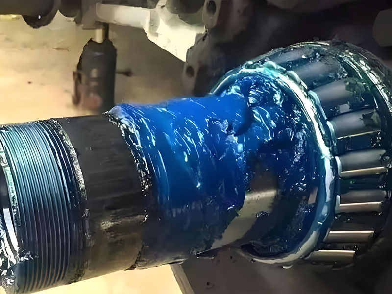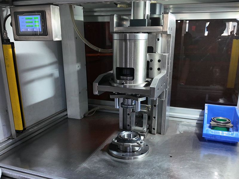
Quick Answer: A press fit is an assembly method that joins two parts by controlled interference. The hole is slightly smaller than the shaft or mating part, so forcing them together creates contact pressure and friction. That friction resists axial movement and torque without a separate fastener. Press fits are common in shaft-hub joints, bushings, pins, and bearing rings, but they depend on correct tolerances, materials, surface condition, and installation method.
A press fit is one of the simplest ways to join parts, but it is also one of the easiest to get wrong. The joint looks like two plain cylindrical parts, yet its performance depends on the specified interference, the resulting contact pressure, the friction at the interface, and the stresses that assembly and service create. This article explains what a press fit is, how it works, how interference is specified, and what to check before using one in a shaft-hub joint or a bearing application.
Press Fit at a Glance
A press fit is a joining method in which one part is forced into another with a controlled size difference. Before assembly, the hole is smaller than the shaft or mating part. That size difference is the interference, and it is what creates the grip after the parts are pressed together.
Press fits appear in many mechanical assemblies, including:
- Shaft-hub joints that transmit torque or axial load.
- Bearing inner rings fitted to shafts and outer rings fitted to housings.
- Bushings, pins, sleeves, and insert-type joints.
A press fit performs reliably when the tolerances, materials, surface condition, and assembly method are correctly matched. A press fit is not just a tight hole; it is a designed interference joint with a required holding capacity and an allowable stress limit.
Use a press fit when the joint must transmit torque, axial load, or maintain alignment without separate fasteners. Do not assume it is suitable for assemblies that need frequent disassembly or for very thin-walled parts without further design checks.
How a Press Fit Works
During assembly, the interference causes elastic deformation of the mating parts. The deformed material creates normal contact pressure around the interface. Friction at that contact surface then resists axial movement and torque.
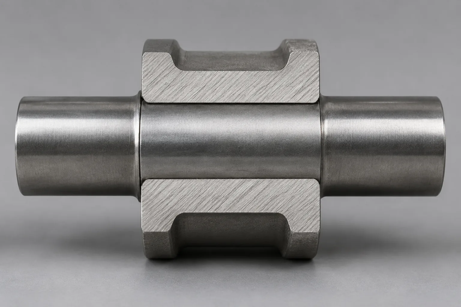
Holding capacity depends on several factors:
- The amount of interference.
- The contact area and contact length.
- The friction coefficient between the materials.
- Material properties, surface finish, and geometry.
- Operating temperature and lubrication.
Holding capacity and assembly force are related but they are not the same design check. The relationship between interference, contact pressure, friction, and load capacity is normally evaluated with engineering equations rather than a single rule of thumb. A joint that holds a high load may also require a high assembly force, and that force can damage the parts if the design does not allow for it.
Very high interference can cause yielding, cracking, galling, or excessive assembly force instead of improving the joint. The design must keep both the contact pressure and the assembly stress within acceptable limits.
Common Press-Fit Configurations
The most recognizable press fit is a cylindrical shaft-hub joint. The shaft is slightly larger than the bore, and the hub is pressed onto the shaft. The same principle appears in bearing inner-ring-to-shaft fits and outer-ring-to-housing fits, where the bearing ring is the part being fitted.
Related configurations include pins, bushings, sleeves, and insert-type joints. In each case, the design intent is to create a controlled interference that holds the parts in position and carries the required load.
Press fit, interference fit, and friction fit are related but not identical terms: press fit describes the mechanical assembly method, interference fit describes the dimensional overlap, and friction fit is a general description of a joint that holds by friction. Shrink fit and expansion fit are thermal or mechanical assembly methods that can create the same interference condition. The distinction matters because the same final fit condition can be produced by mechanical pressing or by thermal methods, and each method has different risks.
Press Fit vs. Shrink Fit vs. Expansion Fit
A press fit uses mechanical forcing at ambient or controlled temperature. The parts are aligned and pressed together with a controlled force.
A shrink fit heats the outer part or cools the inner part to create temporary clearance before assembly. When the parts return to operating temperature, the interference is restored.
An expansion fit uses thermal or mechanical expansion of the outer part to allow assembly. Like a shrink fit, it depends on restoring the intended interference after the parts are positioned.
Thermal methods can reduce assembly force and may be preferred when interference is high or when pressing could damage sensitive components. They also add temperature control and safety requirements. Temperature changes may alter material properties, bearing clearance, lubrication, or preload, so verify the method before use.
How Interference and Fit Are Specified
A press-fit specification normally defines the nominal size, the hole limits, the shaft limits, and the resulting minimum and maximum interference. The designer must know both limits, not just a nominal interference value, because production parts will vary within a tolerance range.
Fits are commonly classified as:
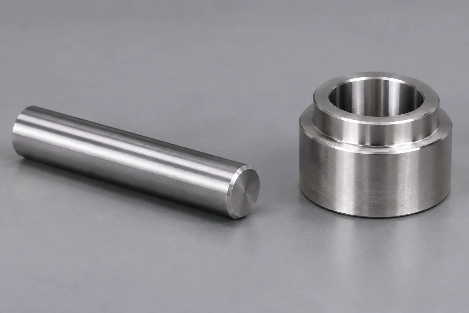
- Clearance fit: the hole is larger than the shaft, so there is clearance before assembly.
- Transition fit: the limits may produce a small clearance or a small interference.
- Interference fit: the hole is smaller than the shaft, so assembly requires force or thermal methods.
Tolerance-class notation is one way to specify hole and shaft limits. The exact designation must be verified against the applicable design rules and the actual application. For example, a designation such as H7/p6 is only an illustrative tolerance-class pair; verify its actual limits and resulting interference against the applicable standard and the actual size. The selected fit must match the required load capacity, stress limits, material, surface finish, and assembly method.
Diametral interference and radial interference must not be confused in calculations. Diametral interference is the difference in diameter; radial interference is half of that difference for a simple cylindrical fit. Using the wrong value changes the calculated contact pressure and can lead to an unsafe design.
Use published design rules or validated company specifications for production. A fit that works for one material or size may be unsuitable for another because yield strength, thermal expansion, or coating thickness can change the result.
Design Checks Before Choosing a Press Fit
Before a press fit is released for production, check the joint as a system. The following checks are essential:
- Check the required torque and axial load capacity with the intended safety factor.
- Check contact pressure and stresses against material yield and fatigue limits.
- Check whether the joined parts can withstand assembly force without buckling, cracking, or distortion.
- Consider operating temperature, differential expansion, corrosion, surface finish, lubrication, coatings, and contamination.
- Consider disassembly requirements and whether the joint must be serviceable.
- For bearings, check how the fit affects internal clearance, preload, ring stress, and rotation conditions.
Required safety factors and allowable stresses should come from design rules, company rules, or validated calculations. They should not be guessed from a similar joint without checking the actual materials and loads.
Thin-walled parts, plastics, coated parts, and heat-treated components may require modified calculation methods or testing. Their behavior can differ from a solid steel shaft-hub joint, especially when assembly force or thermal expansion is significant.
Calculating Press-Fit Holding Force and Stress
A press-fit calculation needs several inputs: nominal diameter, interference, contact length, material elastic properties, friction coefficient, and surface condition. The general path is to convert interference into contact pressure, then use contact pressure and friction to estimate axial holding force or torque capacity.
For cylindrical press fits, thick-wall cylinder equations are a common engineering approach. Assembly force is estimated from contact pressure, friction, and interface geometry. The same calculation must include a check that the calculated stresses remain below allowable values.
Equations and allowable values must be sourced or derived and checked by a qualified engineer. Friction coefficient ranges depend on the material pair, lubrication, surface finish, and contamination, so a value should not be published or reused without a reliable source and a matching application.
Thermal effects can change interference during operation. A joint that is correct at room temperature may lose interference or become overstressed when the parts reach operating temperature. Simplified equations may not apply to tapered fits, very short hubs, plastic parts, coated surfaces, or non-uniform contact.
Installing a Press Fit
Installation controls whether the designed interference becomes a reliable joint or a damaged assembly. A practical sequence is:
- Check dimensions, cleanliness, burrs, chamfers, and surface condition before assembly.
- Align the parts before applying force to avoid cocking, galling, and localized damage.
- Use a controlled press or thermal method rather than uncontrolled impact where possible.
- Apply force through the part being fitted and avoid transmitting assembly force through sensitive elements such as bearing rolling elements.
- Monitor force, displacement, or temperature where the application requires process control.
- Use lubrication only when it is compatible with the design assumptions and the final application.
Use thermal assembly when the component manufacturer recommends it or when press force would exceed safe limits. Some bearings, seals, coatings, or clean-room assemblies have specific restrictions on heating, cooling, or lubricants, so the component instructions take priority over general workshop practice.
Inspecting and Troubleshooting Press Fits
Inspection starts before assembly. Verify the shaft and housing dimensions, the tolerance grades, and the specified interference range. After assembly, check for proper seating, alignment, and the absence of cracks or deformation.
In service, look for signs of:
- Slipping or loosening at the joint.
- Fretting, galling, or bore discoloration.
- Corrosion or surface damage at the interface.
- Cracking or deformation of the hub or ring.
- Abnormal vibration or noise.
Confirm that assembly force or temperature records are within the approved process window. Acceptance criteria and inspection frequency should be defined by the design specification or quality plan. When a joint fails, investigate the fit tolerance, surface finish, material condition, assembly method, and operating loads together. A press fit that appears correct at assembly can still loosen under thermal cycling, vibration, or insufficient interference.
Advantages and Limitations of Press Fits
Press fits have clear advantages when the application suits them:
- No separate fastener is required.
- Good concentricity potential when the parts are accurately made.
- High torque and axial load capacity when correctly designed.
- Familiar manufacturing and assembly methods.
The limitations are equally important:
- Tight tolerance requirements increase manufacturing cost.
- High assembly force can damage parts or tooling.
- Surface damage, galling, and cracking are possible.
- Disassembly is difficult and may destroy the fit.
- Stress concentration and sensitivity to material and temperature must be managed.
Press fits are best selected when the joint is intended to be semi-permanent or permanent. They are not the first choice when frequent service disassembly is required. Compared with keyed, splined, threaded, adhesive, and welded joints, a press fit is compact and avoids extra features, but it offers less adjustment and can be less forgiving of tolerance errors. Avoid or redesign the joint when very thin sections, brittle materials, or uncertain tolerances make the fit unreliable.
Press Fits in Bearing Applications
Bearing inner rings are commonly fitted to shafts and outer rings to housings using selected interference or transition fits. The fit choice depends on load direction, rotation, load magnitude, temperature, housing material, and whether the ring is rotating or stationary relative to the load.
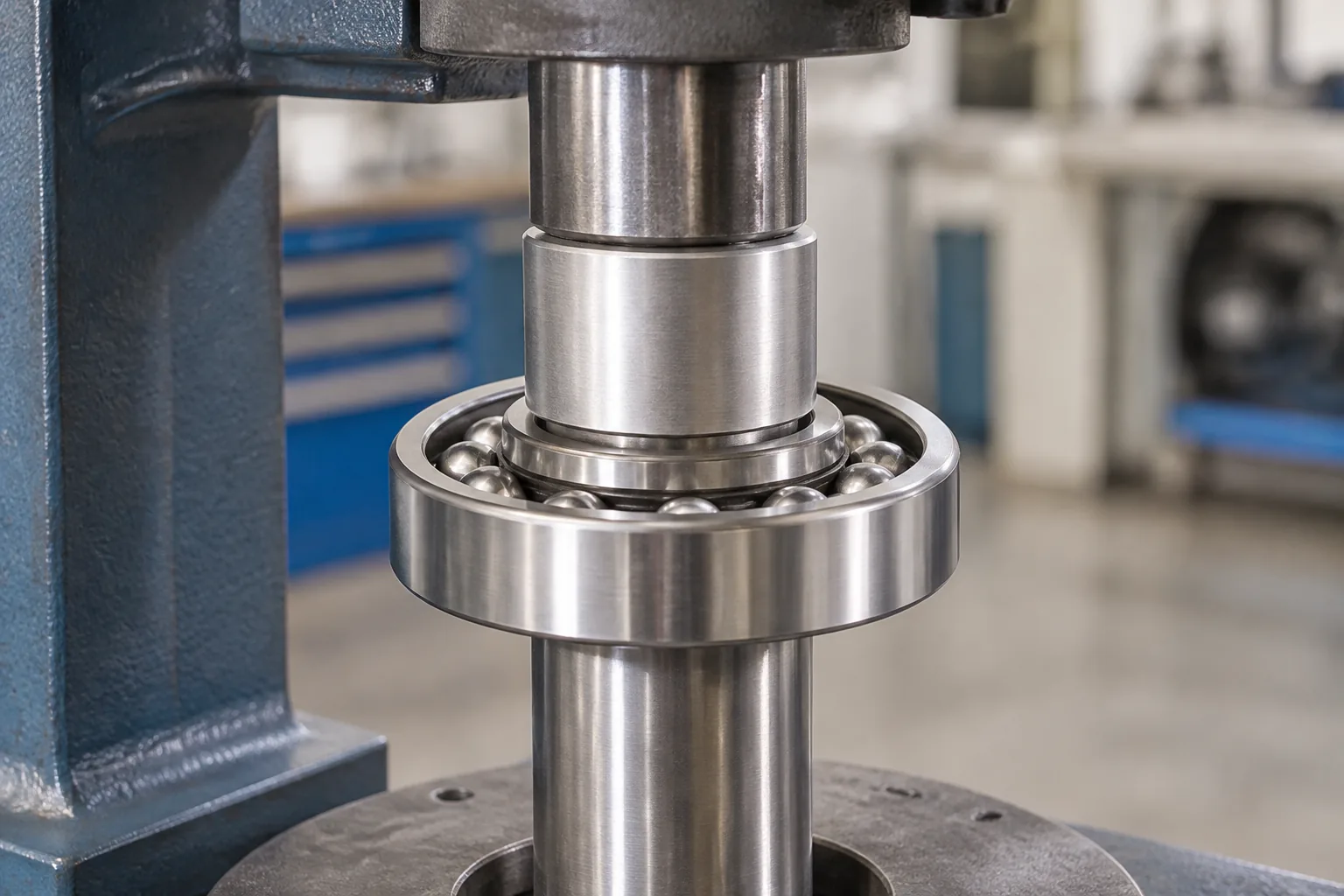
Mounting force should be applied to the ring being fitted and should not pass through the rolling elements. If the inner ring is being fitted to a shaft, press on the inner ring. If the outer ring is being fitted into a housing, press on the outer ring. Transmitting force through the balls or rollers can damage the raceways even when the bearing later appears to turn freely.
Interference affects bearing internal clearance and preload, so fit selection must be coordinated with bearing requirements. Excessive interference can distort raceways, reduce internal clearance, and raise ring stress. Insufficient interference can permit micromovement, fretting, and ring creep. Incorrect fits can cause ring creep, fretting, excessive clearance, overheating, or premature failure.
Thermal mounting and controlled disassembly methods are common bearing installation practices where appropriate. Specific fit tables and allowable interference values should come from the bearing manufacturer or the applicable design rules. Bearing damage classification methods can support identification, but they do not replace a fit calculation for the actual application. Split housings, thin-walled bearings, ceramic bearings, and high-temperature applications may require special fit rules.
Conclusion
A press fit is a controlled interference joint that depends on correct tolerances, stress checks, installation, and inspection. It can transmit torque and axial load without a separate fastener, but it is not a universal solution. The fit must be verified for the specific materials, loads, temperatures, surface conditions, and components in the application.
Before production use, confirm the interference limits and allowable stresses with applicable design rules, validated calculations, and component-manufacturer instructions. A press fit that is correct on paper still needs clean assembly, proper alignment, controlled force, and a defined inspection plan to perform reliably in service.
FAQs
Q1: What is the difference between a press fit and an interference fit?
A: An interference fit is the condition in which the mating parts overlap in size before assembly. A press fit is the mechanical assembly method used to force those parts together at ambient or controlled temperature. The terms are often used together because a press fit depends on interference, but press fit describes the process while interference fit describes the fit condition.
Q2: How much interference should a press fit have?
A: There is no universal value. Required interference depends on diameter, contact length, materials, surface finish, friction, load, safety factor, and allowable stress. It should come from a validated calculation or the component manufacturer’s specification for the actual application. Do not copy a value from a different size or material.
Q3: Can a press fit be removed and reused?
A: A press fit can be disassembled, but the joint is usually intended to be semi-permanent or permanent. Removal can damage the bore, shaft, coating, or bearing ring, and the original interference may be lost. Inspect both parts after removal and replace damaged components rather than assuming the joint can be reused.
Q4: What causes a press fit to fail?
A: Common causes include insufficient interference, excessive interference, poor surface finish, contamination, wrong material condition, misalignment during assembly, and thermal cycling or vibration in service. Failures can appear as slipping, fretting, galling, discoloration, cracking, loosening, or abnormal vibration. Diagnose the fit, assembly records, and operating loads together.
Q5: Is lubrication needed for press fitting?
A: Lubrication is not automatically required and can be harmful if the design assumes dry friction or if the lubricant contaminates a bearing, seal, or clean assembly. Use lubrication only when it is compatible with the design assumptions and the final application. Confirm that the friction coefficient used in the calculation matches the assembly condition.
Q6: What is the difference between press fit and shrink fit?
A: A press fit uses mechanical force at ambient or controlled temperature. A shrink fit uses heating of the outer part or cooling of the inner part to create temporary clearance before assembly. Shrink fits can reduce assembly force, but they add temperature control, safety requirements, and possible changes to material properties, bearing clearance, lubrication, or preload.
Q7: Can you press fit a bearing?
A: Yes, bearings commonly use press fits, but the force must be applied to the ring being fitted and must not pass through the rolling elements. The fit must be selected from the bearing manufacturer’s guidelines for the bearing type, size, load direction, rotation, and housing material. Interference also affects internal clearance and preload, so the fit and bearing requirements must be coordinated.
Q8: How is press-fit holding force calculated?
A: The calculation starts with the specified interference and converts it to contact pressure using the geometry and elastic properties of the parts. Contact pressure and friction are then used to estimate axial holding force or torque capacity. The same check must confirm that stresses remain below allowable values. Thermal effects and surface conditions should be included, and the result should be checked by a qualified engineer.
Q9: Do bearings use press fits?
A: Many do, but not every bearing ring is press fitted. A ring that rotates relative to the load usually needs interference to prevent creep, while a stationary ring may use a transition or clearance fit where the application allows. The final choice comes from the bearing manufacturer’s fit table for the load direction, rotation, load magnitude, temperature, and housing material.
Q10: Should force be applied to the inner ring or outer ring during bearing installation?
A: Apply force to the ring that has the interference fit. If the inner ring is being fitted to a shaft, press on the inner ring. If the outer ring is being fitted into a housing, press on the outer ring. Do not transmit mounting force through the rolling elements, because that can damage the raceways.