Quick Answer: Measuring flange runout starts by deciding which measurement you need. On a rotating flange, read face or peripheral runout against the drawing datum axis with an indicator, and record total indicator reading as the maximum minus the minimum. On a gasketed pressure-boundary flange, inspect the gasket seating surface circumferentially and radially to ASME PCC-1. PCC-1-2022 guidance is less than 0.15 mm (0.006 in.) for hard gaskets and less than 0.25 mm (0.010 in.) for soft gaskets, in both directions.
Measuring flange runout is one of those topics that can send two competent people to different measurements. On a rotating part, the concern is face or peripheral runout relative to a datum axis. On a gasketed pressure-boundary joint, the concern is the flatness of the gasket seating surface around the circumference and across the radius. The drawings, standards, and accept-or-reject limits are not interchangeable.
The sections below separate the two cases, then walk through drawing review, indicator setup, TIR recording, ASME PCC-1 checks, field tool choices, and common errors.
Two Different Measurements Called Flange Runout
Before you mount an indicator or reach for a straightedge, classify the flange. The same words describe different surfaces, different references, and different acceptance rules.
| Situation | What is measured | Primary reference |
|---|---|---|
| Rotating component flange | Face or peripheral runout relative to a datum axis | Drawing runout feature control frame interpreted to ASME Y14.5-2018 (R2024) or ISO 1101:2017 |
| Pressure-boundary gasketed flange | Gasket seating surface flatness in circumferential and radial directions | ASME PCC-1 |
On a pressure-boundary flange, the reading relates to the gasket seating surface and the risk of a leak. On a rotating flange, the reading relates to the part’s rotation about a datum axis. Mixing the two sets of values can produce a false acceptance or a false rejection.
Gasket Seating Surface Flatness on Pressure-Boundary Flanges
On a pressure-boundary bolted flange joint, the gasket seating surface is the sealing face. ASME PCC-1 is an assembly guide for pressure-boundary bolted flange joints. Its scope assumes the gasket sits completely inside the circle formed by the bolt holes and does not contact the flange outside that circle. If the gasket extends beyond that circle or contacts outside it, the joint is outside that guide’s stated scope.
The inspection looks at high and low areas around the circumference and across the radius. Both directions matter because a face can look acceptable in one path and still have a local high spot or a radial tilt that affects sealing.
Face and Peripheral Runout on Rotating Flange Drawings
For a rotating flange, face runout is measured on the flange face, and peripheral runout is measured on the outside diameter or another specified peripheral surface. The acceptance basis is the feature control frame on the drawing: the datum axis, the runout type, whether circular or total, and the tolerance value.
ASME Y14.5-2018 (R2024) is the current ASME drawing interpretation standard listed for GD&T. ISO 1101:2017 covers geometric tolerances for form, orientation, location, and run-out and was confirmed in 2022 as still valid. Do not use the PCC-1 gasket seating surface values to accept or reject a drawing callout for rotating-flange runout.
Reading the Drawing Before Measuring Rotating Flange Runout
Three items on the drawing control the measurement: datum axis, runout type, and tolerance value. Together they determine the fixture setup, the indicator sweep, and the pass-or-fail decision.
Runout type changes the sweep. Circular runout is checked section by section around the part. Total runout requires a continuous sweep over the entire measured surface relative to the datum. The recorded value is the full indicator travel, calculated as maximum reading minus minimum reading.
Circular Runout vs Total Runout
Circular runout and total runout are different callouts, and the drawing must state which one applies. Circular runout evaluates one circular element at a time as the part rotates. Total runout evaluates the entire surface relative to the datum as the indicator sweeps across it.
You cannot substitute one for the other or apply a single tolerance value to both. The difference affects the sweep path and the way the reading is recorded, so confirm the callout before measuring.
Datum Axis and Tolerance Zone
Runout is defined relative to a datum axis. If the measurement spindle or part rotation does not establish that axis correctly, the TIR reading changes even when the surface has not changed. When a drawing shows a runout feature control frame, the specified datum axis is the acceptance basis.
ASME Y14.5-2018 (R2024) and ISO 1101:2017 provide the rules for interpreting the symbol and tolerance zone. The setup must align the rotation axis with the drawing datum or establish it by the drawing’s specified datum features.
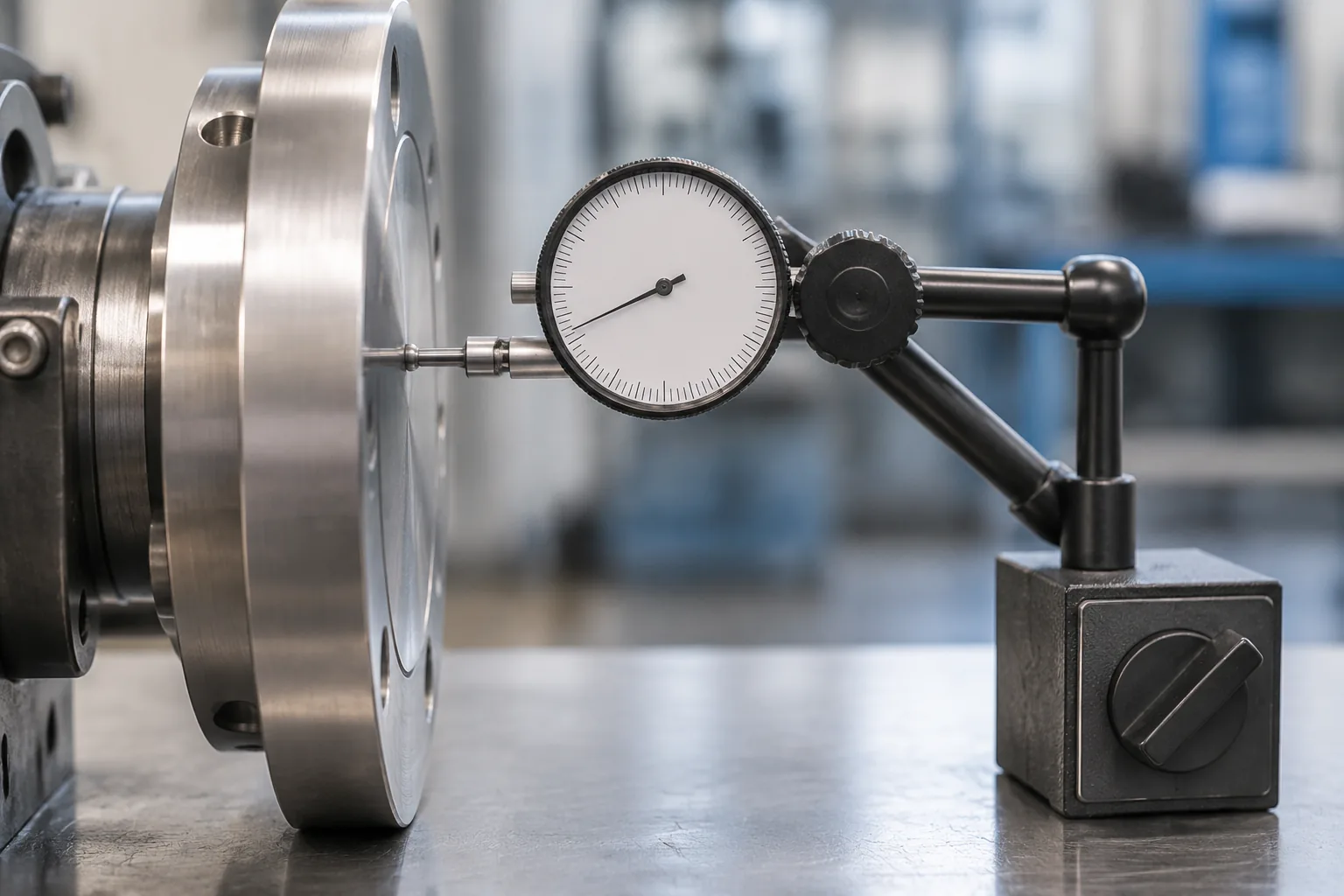
Measuring Face and Peripheral Runout with a Dial Indicator
The basic indicator method is the same for face and peripheral runout, but the contact point changes. On a flange face, the contact runs against the face. On a peripheral surface, the contact runs against the outside diameter or another specified cylindrical surface.
- Establish the datum and mount the part or the measuring spindle so rotation matches the drawing datum.
- Secure the indicator base and position the contact perpendicular to the measured surface.
- Note the starting reading, rotate through at least one full revolution, and watch the maximum and minimum readings.
- Record TIR as maximum minus minimum, along with the measured surface and setup.
Fixturing, Indicator Placement, and Sweep
A loose base, a flexible arm, or a contact that drags can add error larger than the tolerance. Mount the part or the indicator rigidly, keep the contact perpendicular to the surface, and sweep the full circumference. Any movement during the sweep contaminates the reading.
For gasket seating surfaces that require inspection, PCC-1 calls for checking both mating flanges and checking both radial and circumferential directions.
Recording Total Indicator Reading (TIR)
TIR is not a single point reading. It is the full travel spread: maximum value minus minimum value. A digital indicator with max/min hold and runout measurement functions can display difference or total runout as maximum value minus minimum value.
Record the location, the number of revolutions, and the datum setup so another technician can repeat the check.
Checking Gasket Seating Surface Flatness to ASME PCC-1
ASME PCC-1 separates the check into circumferential variation T1 and radial variation T2. Both must be checked. The guidance values in ASME PCC-1-2022, Appendix D, Table D-2-1M / D-2-1 are summarized below.
| Gasket type | T1 circumferential | T2 radial |
|---|---|---|
| Hard gasket | less than 0.15 mm (0.006 in.) | less than 0.15 mm (0.006 in.) |
| Soft gasket | less than 0.25 mm (0.010 in.) | less than 0.25 mm (0.010 in.) |
These values are guidance for gasket seating surface inspection, not a universal manufacturing tolerance that applies automatically to every flange. ASME lists PCC-1-2026 as of 2026; before you cite the table in a specification or acceptance report, check whether the 2026 edition revises this appendix.
Circumferential Variation (T1)
Set four datum points around the circumference and take readings around the full circle. Then move inward 6 mm (0.25 in.) and repeat until the entire gasket seating surface is covered. On each circumferential line, the highest reading minus the lowest reading must be less than T1: less than 0.15 mm (0.006 in.) for hard gaskets and less than 0.25 mm (0.010 in.) for soft gaskets.
Radial Variation (T2)
Set four datum points around the inner edge of the seating surface and take readings radially across the gasket seating surface. Space radial measurement lines at 200 mm (8 in.) or less until the full surface is covered. The spread between the highest and lowest readings along each radial line is compared with T2: less than 0.15 mm (0.006 in.) for hard gaskets and less than 0.25 mm (0.010 in.) for soft gaskets.
Pass-Partition Height and Engineering Judgment
The same table gives guidance for pass-partition surface height P relative to the flange face. For hard gaskets, P should be greater than -0.25 mm and less than 0.0 mm (greater than -0.010 in. and less than 0.0 in.). For soft gaskets, P should be greater than -0.50 mm and less than 0.0 mm (greater than -0.020 in. and less than 0.0 in.).
A value outside the table is not an automatic rejection. Engineering judgment should consider gasket construction, flange flexibility, bolt spacing, leak history, and the consequence of leakage.
Field Methods: Straightedge, Runout Gauge, and Laser
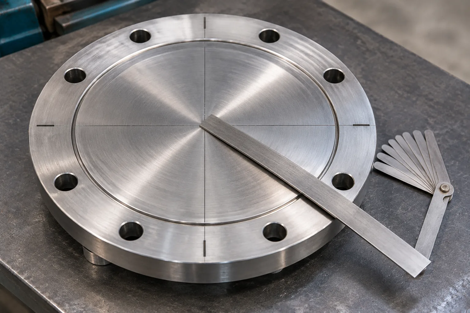
PCC-1 lists three practical methods for checking gasket seating surface flatness: a machinist’s straightedge with feeler gauges, a rigidly mounted flatness or run-out gauge, and laser or field-machining equipment that can provide accurate total indicator readings.
Choose the method by access, flange size, and the reading quality needed. The method must cover both radial and circumferential directions. A straightedge and feeler gauge can reveal local flatness problems but must be used carefully to avoid bridging across high spots. A mounted gauge gives a controlled sweep. Laser or field-machining equipment can handle large or difficult surfaces when it is set up to give reliable readings.
When Flange Runout and Flatness Checks Are Needed
PCC-1 directs the flatness inspection especially to large-diameter flanges, flanges with a leak history, and cases where the surface must be shown to meet a specified flatness requirement.
For product dimensions, materials, pressure-temperature ratings, dimensional tolerances, marking, and testing of pipe flanges, ASME B16.5-2025 is the base standard. That edition was published on May 30, 2025, and covers NPS 1/2-24. Classes 150, 300, 400, 600, 900, and 1500 cover NPS 1/2-24; Class 2500 covers NPS 1/2-12.
For a rotating flange, whether runout is inspected depends on whether the drawing has a runout feature control frame and what it requires.
Common Measurement Errors
- Using PCC-1 gasket seating flatness guidance as a GD&T runout tolerance, or using a drawing runout tolerance as a gasket seating surface limit.
- Stopping before the full gasket seating surface is covered, or spacing radial lines wider than 200 mm (8 in.).
- Building the datum axis incorrectly, leaving the base loose, or tilting the contact so setup error enters the TIR reading.
- Recording a single point instead of maximum minus minimum over the full sweep.
Conclusion
Start by classifying the flange, because measuring flange runout covers two different acceptance problems. For rotating flanges, use the drawing datum axis, runout type, and tolerance to measure face or peripheral runout, and record TIR as maximum minus minimum. For gasketed pressure-boundary flanges, use ASME PCC-1 and check both T1 circumferential variation and T2 radial variation.
The PCC-1-2022 guidance is less than 0.15 mm (0.006 in.) for hard gaskets and less than 0.25 mm (0.010 in.) for soft gaskets in both directions. If a result exceeds the guidance, evaluate gasket construction, flange flexibility, bolt spacing, leak history, and leakage risk before deciding what to do. The safe next step is to confirm the governing drawing or standard edition and then select the measurement method and limit.
FAQs
Q1: Is flange runout the same as flange flatness?
A: No. On a rotating flange, runout is the variation of a face or peripheral surface relative to a datum axis. On a gasketed pressure-boundary flange, the check is gasket seating surface flatness around the circumference and across the radius, evaluated to ASME PCC-1. The terms describe different acceptance questions.
Q2: What runout limits apply to a rotating flange?
A: There is no universal numeric limit. The drawing’s runout feature control frame sets the datum axis, whether the callout is circular or total runout, and the tolerance. Interpret the symbol to ASME Y14.5-2018 (R2024) or ISO 1101:2017 as applicable. Do not substitute the PCC-1 gasket seating values.
Q3: How do you calculate total indicator reading?
A: Subtract the minimum indicator reading from the maximum reading over the full measurement sweep. A digital indicator with max/min hold and runout measurement functions can display difference or total runout as maximum value minus minimum value. Record the setup and sweep so the result can be repeated.
Q4: What flatness limits does ASME PCC-1 give for gasket seating surfaces?
A: In ASME PCC-1-2022, Appendix D, Table D-2-1M / D-2-1, hard gaskets have T1 and T2 less than 0.15 mm (0.006 in.), and soft gaskets have T1 and T2 less than 0.25 mm (0.010 in.). Both the circumferential and radial checks must meet the applicable value. These are inspection guidance values, not universal manufacturing tolerances.
Q5: How many datum points does the PCC-1 circumferential check use?
A: It uses four datum points around the circumference. Take readings around the full circumference, then move inward 6 mm (0.25 in.) and repeat until the entire gasket seating surface is covered. The highest minus lowest reading on each circumferential line must be less than T1.
Q6: What radial line spacing does the PCC-1 radial check require?
A: Space radial measurement lines at 200 mm (8 in.) or less. Set four datum points around the inner edge of the seating surface, take readings radially across the gasket seating surface, and continue until the full surface is covered. Compare the spread on each radial line with T2.
Q7: Can a flange pass a flatness check and still leak?
A: Yes. The PCC-1 table values are guidance, and a surface that meets them can still leak if the joint assembly, gasket, bolting, or operating conditions are unsuitable. If a reading exceeds the table, do not reject the flange automatically; consider gasket construction, flange flexibility, bolt spacing, leak history, and leakage risk.
Q8: Which tools can measure flange-face flatness in the field?
A: ASME PCC-1 lists a machinist’s straightedge with feeler gauges, a rigidly mounted flatness or run-out gauge, and laser or field-machining equipment that provides accurate total indicator readings. Select the method by access, flange size, and the reading quality needed, and cover both radial and circumferential directions.