Quick Answer: Bevel gear types are classified by tooth form and by how their axes relate. Straight bevel gears have straight teeth and run on intersecting axes. Spiral bevel gears use curved, oblique teeth for smoother, quieter meshing on intersecting axes, while hypoid gears run on offset, non-intersecting axes and need lubricants specified for sliding contact. Final selection follows axis layout, load, speed, noise, efficiency, lubrication, and maintenance capability.
Bevel gear types are often discussed as if tooth shape were the main difference. In practice, the shaft layout, tooth form, bearing arrangement, lubrication, and maintenance plan all shape the choice. This guide compares straight bevel, spiral bevel, and hypoid bevel gears across geometry, operating behavior, manufacturing, and application fit. It is a practical selection guide, not a catalog of every gear family.
What Are Bevel Gears?
Bevel gears transmit rotary motion and power between shafts whose axes intersect or are offset. Their pitch surfaces are conical, and the teeth are cut on a cone; the mesh takes place where the pitch cones meet or relate through the designed offset. Tooth form and axis arrangement determine the subtype and much of its operating behavior.
Shaft angle is an application dimension, not a fixed rule. Many drives use a right-angle layout, but bevel gearing can be designed for other angles. Confirm the angle from the housing and gear data rather than assuming a right angle.
Straight, spiral, and hypoid bevel gears belong to the same broad family, but they are not interchangeable in every mounting and lubrication context. A gear set designed for one axis relationship or tooth contact pattern cannot be substituted safely without checking the housing, bearings, backlash, and lubricant requirements.
Straight Bevel Gears
Straight bevel gears have straight teeth that converge toward the pitch-cone apex. They are a comparatively simple bevel gear type for intersecting-axis drives. The subsections below cover their geometry, performance, and typical applications.
Geometry and Tooth Form
Straight bevel teeth are oriented along the pitch-cone element. The pitch cone, apex, face width, and tooth profile define the mesh; the tooth profile changes from the outer end to the inner end, so the geometry must be read as a cone, not a simple cylinder. These gears are commonly associated with intersecting axes. Exact tooth proportions and pitch-cone angles are set by the gear design and should be taken from the applicable drawing or manufacturer data.
Performance Characteristics and Limitations
Straight teeth engage across the face in a way that is easier to inspect than curved-tooth gearing, and the manufacturing route is comparatively straightforward. The trade-off is that straight bevel gears can be less smooth than curved-tooth alternatives, with more sensitivity to noise and vibration at higher operating speeds. Load sharing and contact ratio depend on the design, size, and accuracy of the set. Do not apply a single load or speed limit to all straight bevel gears; use the rating for the specific gear set and application.
Typical Applications
Straight bevel gears are often used for low-to-moderate speed direction changes, simple differentials, hand tools, and industrial machinery where cost and simplicity matter. They fit intersecting-axis layouts and applications with modest smoothness requirements. The mounting must provide the intended shaft relationship and adequate lubrication; if the drive needs quieter running or higher load sharing, a curved-tooth option may be more appropriate.
Spiral Bevel Gears
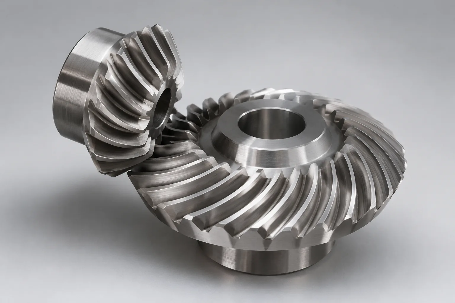
Spiral bevel gears have curved, oblique teeth that engage progressively rather than across the full face at once. That gradual engagement makes them a smoother-running option for intersecting-axis drives compared with straight bevel gears. Geometry, performance, and applications follow.
Geometry and Tooth Curvature
Spiral bevel teeth are curved and inclined relative to the pitch-cone element. The spiral angle and face contact shape how load is shared across the tooth; a well-designed contact pattern distributes load over more than a single line of contact. Spiral bevel gears normally operate on intersecting axes, unlike hypoid gears, which use an offset. Typical spiral angles vary by design and application. The angle affects contact ratio and thrust load, so it should be confirmed from the gear data rather than assumed.
Performance Characteristics and Limitations
Spiral bevel gears generally mesh more smoothly than straight bevel gears, with a higher contact ratio and quieter running in many drives. They can offer better load capacity and noise behavior than straight bevel gears of comparable size, but the result depends on design, manufacturing accuracy, lubrication, and operating conditions. Curved teeth produce axial thrust, so the shaft and bearing arrangement must handle the thrust direction and magnitude. Manufacturing and inspection are more complex than for straight bevel gears, and the contact pattern must be set correctly. Efficiency and noise comparisons should be based on the specific gear set and application data, not on tooth type alone.
Typical Applications
Spiral bevel gears are common in automotive differentials, industrial gearboxes, machine tools, and drives that need smoother operation on intersecting axes. Application choice depends on speed, load, noise targets, and the available bearing support. A spiral bevel set is a practical fit when the axis layout is intersecting and the drive benefits from gradual tooth engagement.
Hypoid Bevel Gears
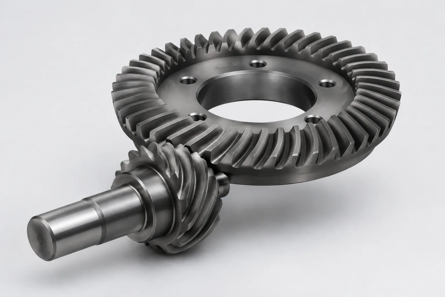
Hypoid gears are bevel-type gears whose axes are offset and non-intersecting. The offset changes the sliding behavior at the mesh, the mounting layout, and the lubrication requirements compared with spiral bevel gears. Geometry, performance, and applications follow.
Geometry and Offset Axes
Hypoid gearing uses an offset between the pinion axis and the gear axis. The tooth form is spiral-like, but the offset means the teeth slide as they mesh rather than rolling in the same way as an intersecting-axis spiral bevel set. Hypoid gears are not simply spiral bevel gears with a different name; the axis offset is a real design difference. Offset is a design dimension defined by the application. It should be read from the drawing, gear data, or axle specification, not estimated from the housing.
Performance, Lubrication, and Limitations
Hypoid axles are often chosen where a compact layout and quiet running are important, especially in vehicle axle drives with high ratio reduction. The sliding action at the mesh places specific demands on lubrication and lubricant selection. Efficiency and wear behavior depend on the design, lubricant, setup, and operating conditions, so they should be checked against the application data rather than assumed from the gear type. Use lubricants and maintenance practices specified for hypoid sliding contact. A lubricant intended for a simple spiral bevel set is not automatically suitable for a hypoid set.
Typical Applications
Hypoid gears are widely used in vehicle rear axles and other drives where an offset axis improves packaging. The layout allows the pinion to sit below or above the gear centerline, which can help with body clearance and driveline packaging. Application choice still depends on ratio, lubrication, noise targets, bearing arrangement, and the service environment.
Straight vs Spiral vs Hypoid: Comparison
The table gives a practical, qualitative comparison. It is a starting point for layout and duty discussion, not a substitute for the gear rating and housing design.
| Feature | Straight bevel | Spiral bevel | Hypoid |
|---|---|---|---|
| Axis relationship | Intersecting axes; simpler layout | Intersecting axes; layout must support thrust | Offset, non-intersecting axes |
| Tooth form | Straight teeth along the pitch-cone element | Curved, oblique teeth | Spiral-like teeth with offset sliding |
| Engagement | Direct face contact; less gradual | Progressive engagement | Progressive engagement with sliding |
| Operating traits | Simple; less smooth at higher speeds | Smoother; good load sharing; produces thrust | Compact layout; quiet running potential; lubrication sensitive |
| Lubrication focus | General gear lubrication for the application | Lubricant and thrust bearings matched to the application | Hypoid-specific lubricant and careful setup |
| Typical fit | Low-to-moderate speed, cost-sensitive intersecting drives | Smoother intersecting-axis drives | Offset-axis axle and drive packaging |
The comparison is qualitative. Final selection depends on the complete drive system, not tooth type alone.
Axis Relationship and Tooth Geometry
Straight bevel and spiral bevel gears are both used on intersecting axes; the difference is tooth form. Straight teeth lie along the pitch-cone element, while spiral teeth are curved and inclined. Hypoid gears also use a spiral-like tooth form, but the pinion axis is offset from the gear axis. That offset is the key geometric distinction from spiral bevel gears.
The axis relationship should be confirmed before comparing tooth-level performance. A housing designed for an offset hypoid set may not accept an intersecting-axis spiral set without major changes, and the reverse is also true.
Load, Speed, Noise, and Efficiency
General trends are useful: straight bevel gears are simpler and often suited to less demanding drives; spiral bevel gears improve smoothness and load sharing on intersecting axes; hypoid gears support offset packaging and quiet axle layouts but introduce sliding contact. These are trends, not universal limits. Load capacity, speed, noise, and efficiency depend on size, accuracy, heat treatment, lubrication, bearing support, and the operating point. Use the manufacturer’s rating and application calculation for actual limits. A gear type that is quieter in one installation can be noisier in another if the contact pattern, backlash, or bearing preload is wrong.
Cost, Manufacturing, and Lubrication
Straight bevel gears usually involve a comparatively simple tooth form to cut and inspect. Spiral bevel gears need curved-tooth production and contact-pattern work. Hypoid gears add offset-axis setup and sliding-contact lubrication requirements, so they generally demand more specialized manufacturing and service attention. Spiral and hypoid sets produce thrust loads, so bearings and housing stiffness must be part of the cost comparison. Hypoid gearing also requires application-specific lubricant attention; the lubricant decision should not be treated as a generic gear-oil choice.
How to Choose the Right Bevel Gear Type
Start with the drive layout, then compare tooth-level performance. The gear type must fit the housing, bearings, ratio, lubrication, and maintenance environment; a gear that performs well on paper but cannot be set up or serviced correctly is a poor choice.
Application Requirements and Axis Layout
Start by deciding whether the design requires intersecting axes or can accommodate offset axes. Check the following before comparing tooth forms:
- Available space
- Required ratio
- Mounting position
- Bearing arrangement
Axis layout is a primary filter because it determines which gear types can physically fit and how the pinion and gear will be supported.
Load, Speed, Noise, and Efficiency Targets
Match straight bevel gears to simpler, less demanding drives where cost and simplicity matter. Consider spiral bevel gears when smoother operation and load sharing are priorities on intersecting axes. Consider hypoid gears when offset-axis packaging and quiet operation are important, subject to lubrication and efficiency checks. Use manufacturer ratings and application-specific calculations for final sizing. Do not size a gear from a generic comparison table or from another machine’s experience.
Cost, Availability, and Maintenance Constraints
Weigh manufacturing complexity, lead time, lubricant requirements, and inspection capability. Total lifecycle cost matters more than purchase price alone: a low-cost gear that needs frequent adjustment or a special lubricant can be more expensive to own. Maintenance teams must be equipped to set backlash, verify contact pattern, and apply the correct lubricant.
Design and Manufacturing Considerations
Several design and production factors affect whether a bevel gear type performs as intended. This section focuses on type-related implications, not a full gear-design tutorial. Claims about load capacity, life, or process capability should be checked against technical references or manufacturer data.
Cutting, Grinding, and Tooth Finishing
Straight bevel teeth are comparatively straightforward to cut and inspect. Spiral bevel teeth require curved-tooth production and careful contact-pattern development. Hypoid teeth add offset-axis geometry, so production and inspection are generally more specialized. Grinding and tooth finishing can improve accuracy and surface condition, but the process must suit the gear type and duty.
Materials, Heat Treatment, and Contact Pattern
Materials and heat treatment influence load capacity and durability in all three types. Case hardening, through hardening, and other treatments are selected for the duty, not simply for the tooth form. Contact pattern and backlash setup are especially critical for spiral and hypoid gears because the mesh is sensitive to position and deflection. Do not prescribe a material grade without application data; the drawing, load case, and manufacturing specification should govern.
Installation, Lubrication, and Maintenance Notes
Bevel gear type selection is not the whole job; installation and maintenance strongly affect whether the gear set reaches its intended life. Focus on alignment, bearing preload, backlash, contact pattern, and lubricant compatibility.
Alignment, Backlash, and Contact Pattern Checks
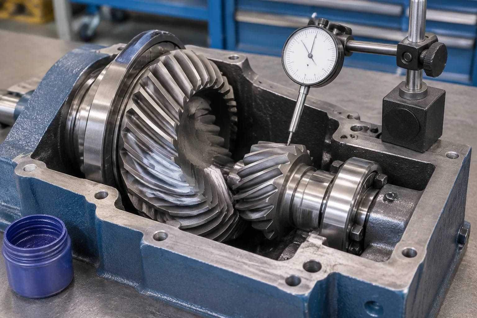
Shaft alignment and bearing support affect tooth contact and noise. A gear set that is correctly manufactured can still run poorly if the pinion and gear are misaligned or the bearings allow deflection under load. Backlash and contact-pattern checks are setup and maintenance verification steps. Incorrect setup can cause premature wear regardless of gear type. Follow the gear manufacturer’s specified setup tolerances and inspection method. Do not substitute a generic backlash value from another application.
Lubrication and Wear Inspection
General gear lubrication needs differ from hypoid-specific requirements. Hypoid sliding contact needs a lubricant and service practice specified for that application. Inspect for wear, scoring, pitting, and abnormal noise; these are triggers for diagnosis, not proof of a single cause. Use the lubricant and change interval specified for the application. Do not assume a lubricant suitable for spiral bevel gears is automatically suitable for hypoid gears.
Terminology and Standards to Reference
Clear terms reduce selection errors. The pitch cone is the cone that defines the gear’s pitch surface. Spiral angle describes the inclination of the tooth trace. Offset is the distance between the pinion and gear axes in a hypoid set. Contact ratio describes the average number of tooth pairs in contact; a higher contact ratio generally supports smoother load transfer. Backlash is the clearance between mating teeth. Contact pattern is the area where the teeth touch under load or check conditions.
Use ISO 23509-1 for bevel-gear geometry, ISO 10300 for load-capacity rating, and manufacturer documentation for definitions, accuracy, application limits, and assembly checks. Use consistent terminology: spiral bevel gears are not hypoid gears, and a hypoid set should not be described as a simple spiral bevel set with an offset.
Conclusion
Bevel gear types differ in more than tooth shape. Straight bevel gears are the simpler intersecting-axis choice; spiral bevel gears add smoother meshing and load sharing on intersecting axes; hypoid gears use offset axes and demand application-specific lubrication and setup. The right selection follows axis layout, load, speed, noise, efficiency, bearing arrangement, and maintenance capability. Confirm the final gear type and rating with the housing, gear data, and manufacturer’s application information before ordering or rebuilding a drive.
FAQs
Q1: Are spiral bevel gears and hypoid gears interchangeable?
A: No. A spiral bevel set runs on intersecting axes, while a hypoid set uses offset, non-intersecting axes. The housing, bearings, backlash, contact pattern, and lubricant requirements differ, so one type cannot be substituted for the other without a full design check.
Q2: Do straight bevel gears always run at a right angle?
A: No. A right-angle layout is common, but the shaft angle is an application dimension. Confirm the required angle, pitch cones, and mounting from the gear data and housing rather than assuming a right angle.
Q3: What lubricant should a hypoid gear use?
A: Use the lubricant specified for the hypoid application and its sliding contact conditions. A fluid intended for a simple spiral bevel set is not automatically suitable. Follow the equipment or gear manufacturer’s viscosity, additive, and service-interval requirements.
Q4: Which setup checks matter most for spiral and hypoid gears?
A: Check shaft alignment, bearing preload, backlash, and tooth contact pattern. These checks confirm that the gear set is positioned as designed and that load is shared across the intended contact area. Use the manufacturer’s tolerances and inspection method.
Q5: Can I choose a bevel gear type by load rating alone?
A: No. Load rating is not enough on its own. Axis layout, housing space, bearings, speed, noise, efficiency, lubrication, and maintenance capability can rule out a type before rating is compared. Select the type that fits the complete drive system, then confirm the rating for that application.