Quick Answer
Installing a thrust bearing correctly requires a clean workspace, proper tools (press or fitting tool, never a hammer), and even force applied only through the race ring. After mounting, verify alignment with a dial indicator, apply the correct lubricant quantity (fill 30–50% of internal space for grease), and perform a run-in check at low speed. Ongoing maintenance includes regular temperature monitoring, noise checks, and re-greasing based on operating conditions.
A thrust bearing that fails prematurely often points back to the installation process. Even a high-quality bearing will underperform if mounted incorrectly or neglected afterward. Unplanned downtime, repair costs, and damage to adjacent components are the usual consequences.
This guide covers the complete lifecycle: pre-installation checks, mounting procedures for each component, alignment verification, lubrication, common pitfalls, and a practical maintenance schedule. The goal is to help you achieve the full design life of your thrust bearing—typically tens of thousands of operating hours under proper conditions.
Why Correct Installation and Maintenance Are Critical
Poor installation is responsible for a significant portion of premature bearing failures. The real cost extends far beyond the replacement part:
- Unplanned production stoppages – machinery sits idle while repairs are made.
- Emergency maintenance expenses – after-hours labor and expedited shipping add up.
- Secondary damage – a failed bearing can score the shaft, damage the housing, and contaminate the entire lubrication system.
- Missed delivery commitments – extended downtime affects customer trust and revenue.
Conversely, a correctly installed and well-maintained bearing reaches its rated service life consistently. The effort invested in proper procedures pays back many times over through reliable operation.
Pre-Installation Preparation
Preparation determines the outcome. Never rush this phase.
Cleanliness is mandatory. The installation area must be free of dust, dirt, and metal filings. Even particles invisible to the naked eye cause abrasive wear or brinelling. Use a clean, covered workbench and lint-free cloths. Keep the bearing in its sealed packaging until the moment of mounting.
Required tools and equipment:
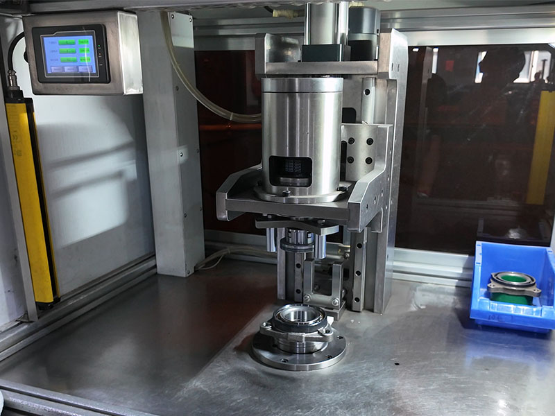
- Mechanical or hydraulic press (or a bearing fitting tool set)
- Dial indicator with magnetic base
- Torque wrench (calibrated)
- Feeler gauge set
- Induction heater (for interference-fit assemblies)
- Clean solvent and lint-free wipes
- Approved grease or oil (as specified by the bearing manufacturer)
- Protective gloves and safety glasses
Inspect all components before starting:
- Bearing – check for shipping damage (dents, rust, corrosion). Verify the part number and dimensions match your specifications. Confirm that the anti-corrosion coating is intact.
- Shaft – measure the journal diameter and compare with the bearing bore tolerance. Remove burrs or scratches with fine emery paper. Wipe clean with solvent.
- Housing – check the bore diameter and roundness. Ensure the housing shoulder is clean and free of nicks.
All parts must be dry and at ambient temperature (typically 20–25°C) unless you are using controlled heating for interference fits.
Step-by-Step Thrust Bearing Installation
Follow this sequence carefully. Each step builds on the previous one.
Mounting the Stationary Race (Housing Washer)
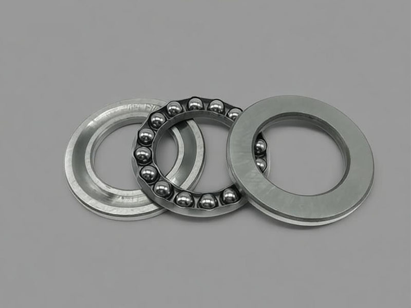
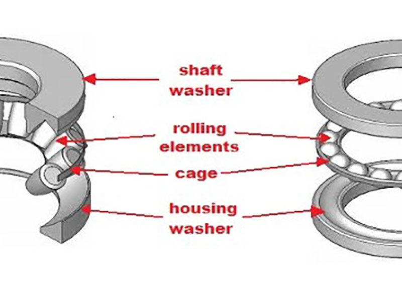
The stationary race fixes into the housing bore. For single-direction thrust ball bearings, identify the correct ring: the shaft washer has a smaller ground bore, while the housing washer has a larger bore and fits loosely in the housing.
Procedure:
- Position the housing washer squarely against the housing shoulder.
- Use a press or a fitting tool that contacts the entire circumference of the race. Never use a hammer or punch on a single point.
- Apply force only to the ring being mounted. Do not transmit force through the rolling elements—this creates brinelling dents.
- For interference fits, heat the housing uniformly to 80–90°C (176–194°F) using an induction heater or oven. Do not exceed 120°C (248°F), as this may alter the material’s temper.
- Press the race fully home until it seats solidly against the shoulder. Use a feeler gauge to check for gaps—there should be none.
Mounting the Rotating Race (Shaft Washer)
The shaft washer attaches to the rotating shaft. This step requires equal care.
Procedure:
- Wipe the shaft seating surface with solvent and a lint-free cloth.
- Slide the shaft washer onto the shaft and position it against the shaft shoulder or retaining ring.
- Apply even, circumferential force using a press or fitting tool. The force must act on the shaft washer only.
- For tapered shafts, follow the manufacturer’s tightening sequence. Typically, you will use a locknut with a specified torque value. Tighten progressively in a star pattern if multiple fasteners are involved.
- After mounting, check that the washer does not rock or tilt on the shaft.
Applying Preload (When Required)
Preload is a controlled axial force that removes internal clearance. It is essential for high-speed spindles, precision machine tools, and applications requiring high rigidity.
When to preload:
- High rotational speeds where centrifugal forces affect ball behavior.
- Applications demanding minimal axial deflection under load.
- Systems requiring low vibration and noise levels.
How to apply preload:
- Use precision shims between the housing and the stationary race.
- Use a locknut with a calibrated torque wrench on the shaft.
- Use spring mechanisms that provide consistent preload despite thermal expansion.
Measurement and verification:
- Measure axial displacement with a dial indicator as you tighten.
- Refer to the bearing manufacturer’s data sheet for the preload force value (often given in Newtons or pounds).
- Warning: Excessive preload causes overheating and fatigue failure. Insufficient preload leads to vibration, skidding, and reduced rigidity. Follow the specification exactly.
Alignment Verification
Misalignment is a primary cause of premature thrust bearing failure. Verify alignment immediately after mounting.
Checking shaft and housing alignment:
- Mount a dial indicator on the housing with the probe contacting the shaft shoulder.
- Rotate the shaft slowly through one full revolution.
- Record the total indicated runout (TIR). For most industrial applications, the acceptable limit is 0.01–0.05 mm (0.0004–0.002 inches), depending on bearing size and precision grade.
- Also check that the housing bore axis is collinear with the shaft axis.
Checking the bearing itself:
- Rotate the shaft by hand—it should turn smoothly with no binding or rough spots.
- Listen for unusual noises (grinding, clicking, or rattling).
- For separable thrust bearings, verify that the two race faces are parallel using a dial indicator.
Interpreting a misaligned wear path (visible only after operation, but keep in mind during installation): A path that runs diagonally from one side of the race to the other indicates misalignment. This condition generates high localized stresses, raises operating temperatures, and degrades lubricant quickly.
Lubrication Application
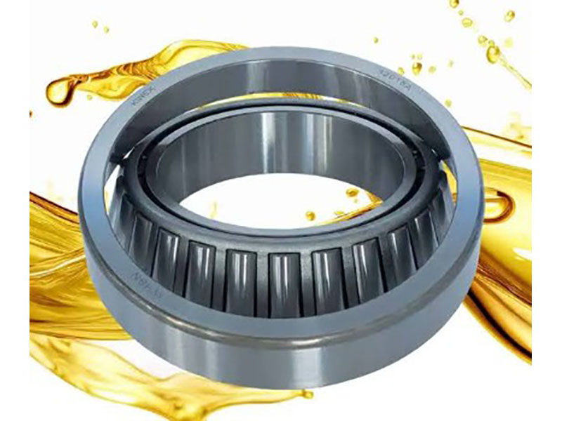
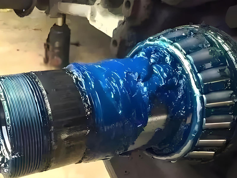
Lubrication is the single most influential factor in bearing life after installation. The right lubricant, in the right quantity, applied correctly, is non-negotiable.
Grease lubrication – quantity:
- Fill 30% to 50% of the bearing’s internal free space with grease.
- Under-greasing causes metal-to-metal contact and rapid wear.
- Over-greasing causes churning, excessive temperature rise, and seal damage.
- For re-greasing calculations, the industry-standard SKF formula is practical:
Grease quantity (ounces) = Bearing outside diameter (inches) × Bearing height (inches) × 0.114
For metric users, this translates to roughly 0.005 × (OD in mm) × (height in mm) in grams—but always verify with your lubricant supplier.
Oil lubrication – viscosity and flow:
- For oil-mist or circulating oil systems, select the ISO viscosity grade based on operating speed and temperature.
- ISO VG 68 is typical for moderate speeds and temperatures.
- ISO VG 150 to 220 is used for heavy loads, low speeds, or high ambient temperatures.
- Ensure the oil is clean (filtration down to at least 10 microns) and flows continuously to the thrust face for flood-lubricated systems.
- For high-speed directed lubrication, aim the oil jet directly at the rolling element inlet.
Final Checks After Mounting
After applying lubricant and before starting the machine, perform these final checks:
- Rotate the shaft by hand through several full revolutions. The motion should be smooth, with no binding, grinding, or rattling.
- If you feel resistance or hear unusual sounds, stop and investigate. Common causes include misalignment, incorrect race positioning, or foreign debris.
- Verify that all fasteners (locknuts, retaining rings) are tightened to the specified torque.
- Check that seals are properly seated and not rubbing against rotating surfaces.
Run-In Check After Lubrication
- Rotate the shaft several turns by hand to distribute the lubricant evenly.
- Run the machine at 25% of normal operating speed for 15–30 minutes.
- Monitor temperature closely. A mild initial rise is normal, but a sharp increase indicates a problem (binding, misalignment, or excessive grease).
- If temperature stabilizes, gradually increase speed to 50%, then 75%, holding each step for 10 minutes, before reaching full speed.
- Record the stabilized operating temperature as a baseline for future comparisons.
Common Installation Mistakes to Avoid
These six errors account for the majority of installation-related failures.
1. Applying force through the rolling elements.
This is the most damaging error. Never hammer, press, or strike the bearing in a way that transmits load through the balls or rollers. The result is brinelling—permanent indentations that generate vibration and noise. Always apply force solely to the race ring being mounted.
2. Mounting the wrong race.
For single-direction thrust bearings, the shaft washer (smaller bore) must go on the shaft; the housing washer (larger bore) goes into the housing. Reversing them creates a loose fit on the shaft and a tight fit in the housing, leading to rapid seizure.
3. Skipping alignment checks.
Assuming alignment is “good enough” is a gamble. A misaligned bearing will show premature spalling, overheating, and cage damage. Always use a dial indicator—it takes only a few extra minutes.
4. Using incorrect lubricant.
Mixing grease types (e.g., lithium-based with polyurea-based) can cause the thickener to break down, turning the grease into liquid soap. Using oil with the wrong viscosity (too thin or too thick) starves or overheats the bearing. Follow the bearing manufacturer’s recommendation explicitly.
5. Overtightening or undertightening the locknut.
An undertightened nut allows the bearing to shift axially under load. An overtightened nut distorts the raceway, creating localized stress and spalling. Use a torque wrench—do not guess.
6. Neglecting the run-in period.
Going from zero to full speed immediately after installation does not allow the lubricant to distribute or the components to settle. Always perform the progressive speed run-in and monitor temperature throughout.
Best Practices for Ongoing Maintenance
Once the bearing is installed, a proactive maintenance routine keeps it in service for its full design life.
Lubrication Schedule and Re-greasing
Re-greasing frequency depends heavily on operating conditions. The following factors shorten the interval and require more frequent attention:
| Factor | Impact on Re-greasing Interval |
|---|---|
| High operating temperature (>70°C) | Shortens grease life—re-grease more often |
| Dusty or contaminated environment | Requires shorter intervals to flush out particles |
| High moisture or water splash | Degrades grease rapidly—increase frequency |
| High vibration levels | Shears grease structure—shorten interval |
| Vertical shaft orientation | Grease tends to migrate—re-grease more frequently |
| Continuous 24/7 operation | Far more frequent than intermittent use |
Re-greasing procedure:
- Clean the grease fitting thoroughly before connecting the grease gun.
- Pump grease slowly (one stroke per second) to avoid seal blowout.
- Continue until you see fresh grease emerging from the relief valve or seal lip (for bearings equipped with relief).
- Wipe away excess grease—do not leave it caked on the exterior.
- Record the date, quantity, and grease type in the maintenance log.
Flushing after shutdown:
If the machine has been idle for an extended period (e.g., weeks), the lubricant may have settled or oxidized. Before restarting, flush the bearing housing with a light circulating oil to remove condensation and contaminants. Rotate the shaft manually while flushing, then drain completely before refilling with the service lubricant.
Temperature and Noise Monitoring
Temperature tracking:
- Install a fixed thermocouple or use an infrared gun during routine checks.
- A sudden temperature rise of 10–15°C above the established baseline is a red flag. Sustained temperatures above 100°C (212°F) for standard greases indicate imminent lubricant failure.
- For tilting-pad thrust bearings in high-load applications, consider adding an external cooling system if temperatures are consistently near the upper limit.
Noise and vibration analysis:
- Use a mechanic’s stethoscope or an accelerometer.
- A grinding sound often points to contamination.
- A rhythmic knocking suggests brinelling or spalling.
- Velocity-peak vibration readings (measured in mm/s or in/s) that spike indicate shock-loading conditions—inspect immediately.
- Higher baseline vibration levels also mean that more frequent lubrication is required, as the lubricant film must work harder to dampen the oscillations.
Visual Inspection Intervals
Establish a tiered inspection schedule based on criticality.
Daily (operator rounds):
- Touch-check bearing housing temperature (or read thermocouple).
- Check lubricant level in the sight glass or reservoir.
- Listen for any new or unusual sounds.
- Look for oil or grease leaks around seals.
Weekly:
- Inspect seals and shields for cracking, hardening, or wear.
- Check mounting bolts and locknuts for torque retention (mark with paint pen for visual reference).
- Observe the lubricant’s color and consistency through a sampling port—darkening indicates oxidation.
Monthly:
- Take and record vibration readings (velocity and acceleration).
- Look for signs of corrosion (reddish deposits) or discoloration (blue or brown from overheating).
- Ensure all guards and covers are secure and free of debris.
Scheduled overhaul (annually or per operating hours):
- Dismantle the bearing and clean thoroughly in solvent.
- Apply compressed air to dry the components—never spin the bearing with compressed air, as this causes unloaded rolling elements to skid and damage the cage.
- Lubricate with light oil and slowly rotate the race by hand to feel for roughness.
- Inspect raceways, rolling elements, and cage for pitting, spalling, scoring, or cracks.
- If any damage is present, replace the bearing. If the bearing is in good condition, repack with fresh grease and reinstall.
Maintenance Checklist
| Frequency | Action |
|---|---|
| Daily | Check temperature; verify lubricant level; listen for noise; inspect for leaks. |
| Weekly | Inspect seals; check bolt torque; assess lubricant color/condition. |
| Monthly | Record vibration readings; check for corrosion/discoloration; ensure guards secure. |
| Quarterly | Re-grease per schedule; verify alignment with dial indicator; perform detailed visual inspection. |
| Annually (or scheduled) | Dismantle, clean, and inspect all components. Replace if damage found. Document findings. |
Conclusion
Installing and maintaining a thrust bearing is a disciplined process—but not a complicated one. The essentials are straightforward: keep everything clean, use the correct tools, apply force only to the race rings, verify alignment, lubricate with the right product in the right quantity, and monitor temperature and noise regularly.
When you follow these practices, your bearing will achieve its rated service life. When you skip them, you invite premature failure. The cost of a thorough installation and a consistent maintenance schedule is minimal compared to the cost of unplanned downtime and emergency repairs.
For a complete understanding of thrust bearing fundamentals—including types, working principles, and selection criteria—start with our foundational guide: What is a Thrust Bearing. If you encounter failures despite correct installation, our detailed Thrust Bearing Failure Analysis guide will help you diagnose the root cause.
FAQs
Q1: What tools do I need for a thrust bearing installation?
A: You need a press or bearing fitting tool (never a hammer), a dial indicator for alignment, a torque wrench, a feeler gauge, clean solvent, lint-free cloths, and the correct lubricant. For interference fits, an induction heater is required.
Q2: How do I distinguish the shaft washer from the housing washer?
A: For single-direction thrust ball bearings, the shaft washer has a smaller, ground bore. The housing washer has a larger bore and fits loosely in the housing.
Q3: What is the correct grease quantity for a thrust bearing?
A: Fill 30% to 50% of the internal free space with grease. For re-greasing, use the SKF formula: ounce = outside diameter (in inches) × bearing height (in inches) × 0.114.
Q4: What operating temperature is too high for a thrust bearing?
A: For standard grease, sustained temperatures above 100°C (212°F) are a warning. A sudden rise of 10–15°C above your recorded baseline also requires immediate investigation.
Q5: How often should I re-grease a thrust bearing?
A: It depends on temperature, contamination, moisture, vibration, shaft orientation, and runtime. Higher values in any of these factors shorten the interval. Use the manufacturer’s recommendation as a starting point and adjust based on your operating conditions.
Q6: What causes a thrust bearing to run hot immediately after installation?
A: Likely causes include over-greasing (churning loss), excessive preload, misalignment, or a tight fit that reduces internal clearance. Stop the machine and check these items in order before restarting.
Q7: Can I reuse a thrust bearing after removal?
A: Generally, no. Once a bearing has run in, the raceways and rolling elements develop wear patterns specific to that installation. Reusing it in another position risks misalignment and load distribution errors. Replace it with a new bearing.
Q8: What is the most common installation mistake?
A: Applying force through the rolling elements—using a hammer or punch on the wrong ring—causes brinelling dents. Always apply force only to the race ring being mounted.
Q9: How do I check alignment after mounting?
A: Use a dial indicator on the housing, contacting the shaft shoulder. Rotate the shaft and measure runout. Acceptable TIR is typically 0.01–0.05 mm for precision applications. Also check that the housing and shaft axes are collinear.
Q10: What should I do if I find spalling during a scheduled inspection?
A: Spalling (flaking) means fatigue failure has begun. The bearing must be replaced immediately. Also investigate the root cause: was the load too high? Was alignment off? Was lubrication insufficient? Fix the root cause before installing the new bearing.