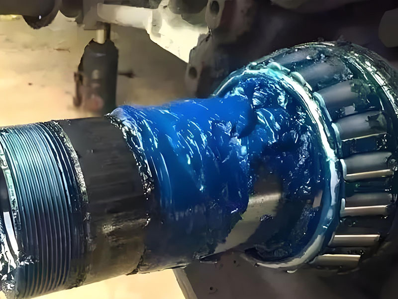
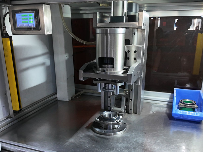
Machining engineers and maintenance teams frequently ask: how can spindle bearings maintain micron-level accuracy while running at high rotational speeds? The answer involves multiple interconnected factors — accuracy class, bearing type, contact angle, preload, lubrication method, and timely replacement.
This article provides a practical guide to selecting and maintaining spindle bearings for optimal speed and accuracy. Key decision points are highlighted throughout, with a summary table and a quick selection checklist at the end for easy reference.
What Are Spindle Bearings?
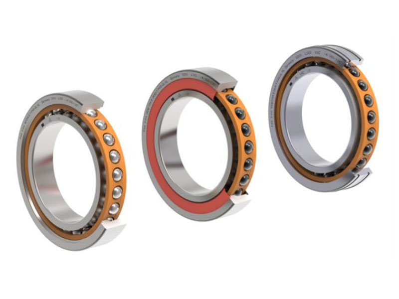
Spindle bearings are high-precision rolling bearings specifically designed for machine tool spindles. Unlike general-purpose bearings, they must sustain high rotational speeds, maintain tight runout tolerances, and resist thermal deformation under variable loads.
The accuracy of spindle bearings directly determines workpiece tolerance, while stiffness affects surface finish quality. For most CNC machining applications, ISO P4 (ABEC-7) precision is the minimum requirement; high-speed machining centers often use P4S or P2 (ABEC-9) bearings.
Two Types of High-Speed Spindle Designs
Belt-driven spindle: The motor connects to the spindle via belts and pulleys. This design isolates bearings from motor heat but introduces belt-related maintenance. Belt-driven spindles are common in conventional milling and turning applications at moderate speeds.
Motorized spindle (electrospindle): The motor rotor is integrated directly into the spindle shaft, eliminating belts and couplings. This design achieves higher speeds and better dynamic balance but subjects bearings to motor heat, requiring sophisticated cooling. Motorized spindles are standard for high-speed precision machining.
Accuracy Classes for Spindle Bearings
Spindle bearings follow international precision standards. The most relevant classes include:
- ISO P4 / ABEC-7: Suitable for most CNC machining, offering tight tolerances for bore diameter, outer diameter, and running accuracy.
- ISO P2 / ABEC-9: Higher precision than P4, used in ultra-high-speed spindles and applications requiring exceptional runout control.
- P4S: According to common industry practice among major European bearing manufacturers, P4S indicates dimensional tolerances meeting ISO P4 while running accuracy meets ISO P2 standards. This combination is widely used in high-speed motorized spindles.
Higher precision reduces runout and vibration, improving machined surface finish and positional accuracy. However, the shaft and housing geometries must match the bearing precision; system runout is the sum of all component tolerances.
Bearing Types for Machine Tool Spindles
Angular Contact Ball Bearings
Angular contact ball bearings are the most common choice for machine tool spindles because they support combined radial and axial loads through a defined contact angle between balls and raceways.
Contact angle determines performance:
- 15° (C): Higher speed capability, lower axial load capacity.
- 25° (E): Higher axial rigidity, moderate speed reduction.
- 30°–40° (BAX series): Maximum axial stiffness for heavy-duty applications.
For most high-speed applications, a 15° contact angle provides the optimal balance between speed and axial capacity.
Hybrid Ceramic Bearings
Hybrid ceramic bearings combine steel rings with silicon nitride (Si₃N₄) ceramic balls. The lower density of ceramic (approx. 40% of steel) reduces centrifugal forces at high speeds, while ceramic’s lower thermal expansion and higher hardness decrease heat generation and wear.
Compared to all-steel bearings, hybrid ceramic bearings generate less heat, offer higher stiffness, and perform better in high-speed, heavy-load electric spindles. They are recommended for motorized spindles operating above DN 2,000,000 under oil-air lubrication.
Cylindrical Roller Bearings
Cylindrical roller bearings use line contact, providing higher radial load capacity than ball bearings. They have limited axial load capability and are typically used in combination with angular contact bearings — cylindrical roller bearings at the rear for radial loads, angular contact bearings at the front for precision and thrust control.
Duplex Arrangements
Angular contact bearings are usually installed in matched sets to increase load capacity and rigidity. Common configurations:
- Back-to-back (DB): Highest moment rigidity, suitable for applications with overturning moments.
- Face-to-face (DF): Accommodates thermal expansion, lower moment rigidity.
- Tandem (DT): Maximum axial load capacity in one direction.
Thrust Ball Bearings
Thrust ball bearings are designed for pure axial loads and handle minimal radial loading. They appear in spindle designs requiring dedicated axial thrust management.
High-Speed Performance Factors
Before selecting lubrication and customization, it is essential to understand the three internal factors that determine a bearing’s high-speed capability.
1. Contact angle and speed trade-off
Lower contact angles (15°) reduce the axial component of ball-raceway forces, allowing higher speeds. For example, reducing the contact angle from 25° to 15° can increase the limiting speed by approximately 20–30%. Conversely, 25° angles provide higher axial stiffness at the expense of speed.
2. Preload selection
Preload eliminates internal clearance and increases system rigidity. Options include:
- Light preload (L): For high-speed applications.
- Medium preload (M): Balanced speed and rigidity.
- Heavy preload (H): For high-load, high-rigidity requirements.
Universal precision bearings with ground end faces allow quick installation without manual preload adjustment. At high speeds, centrifugal forces alter contact angles; proper preload selection maintains stable spindle dynamics.
3. Material – steel vs. ceramic
Ceramic hybrid bearings (silicon nitride balls) significantly reduce centrifugal forces and heat generation. The lower coefficient of thermal expansion maintains preload stability across operating temperature ranges. For spindles running above DN 1,500,000, ceramic hybrids are strongly recommended.
Summary of performance factors:
| Priority | Recommended Configuration |
|---|---|
| Maximum speed | 15° contact angle + light preload + ceramic balls + oil-air lubrication |
| Maximum rigidity | 25° contact angle + medium/heavy preload + steel balls + grease lubrication |
| Longest life (balanced) | P4S accuracy + medium preload + DLR lubrication + scheduled replacement at 15,000 hours |
Lubrication Technologies for High-Speed Spindles
Lubrication is the most critical factor affecting spindle bearing speed capability and service life.
Grease Lubrication
Grease lubrication is simpler and requires no auxiliary equipment. High-quality synthetic greases formulated for spindle bearings are suitable for DN values up to approximately 500,000. Grease-lubricated bearings require periodic regreasing intervals and may overheat at extremely high speeds.
Oil-Air Lubrication
Oil-air lubrication delivers precisely metered oil droplets into a continuous air stream, which carries lubrication directly to bearing contact surfaces. This method supports higher speeds — typically DN values of 1,000,000 to 1,500,000, with advanced systems reaching DN 2,000,000 — by providing consistent lubrication while removing heat. Oil-air systems are standard for motorized spindles operating above 20,000 RPM.
DLR (Direct Lubrication via Outer Ring)
DLR bearings feature oil supply holes machined directly into the outer ring. At high speeds, side-fed lubrication can be blocked by an air curtain effect; direct outer-ring delivery ensures stable lubrication and prevents oil leakage through O-ring seals. DLR designs also eliminate separate oil supply spacers, shortening spindle length and increasing natural frequency.
EDM Holes and Lubrication Grooves
Electrical discharge machining (EDM) produces precision oil holes in bearing rings. Combined with lubrication grooves, these features ensure oil reaches rolling elements regardless of orientation, improving lubrication reliability in vertical or inclined spindle installations.
Customization Options for Spindle Bearings
Standard off-the-shelf bearings can be modified to meet specific spindle requirements. Common modifications include:
- DLR (Direct Lubrication via Outer Ring) with O-ring grooves: See the Lubrication section for detailed benefits. This modification adds outer-ring oil holes and sealing grooves to standard bearings.
- EDM holes for lubrication: Precision-machined oil passageways.
- Inner race reliefs: Reduces stress concentrations at raceway edges.
- ID/OD reductions: Allows fit into non-standard housings or shafts.
- Lubrication grooves and oil holes: Improves lubricant distribution.
- O-ring grooves: Provides sealing to prevent lubricant leakage and contaminant ingress.
- Anti-rotation slots or holes: Prevents outer ring rotation in housing.
- Soft/hardened precision spacers: Controls internal clearance and preload.
- Custom preloads and arrangements: Universal bearings ground for specific preload levels (light, medium, heavy) to eliminate field adjustment.
These modifications transform standard bearings into spindle-specific components while potentially reducing lead times compared to fully custom designs.
Maintenance and Timely Replacement
Signs of Bearing Degradation
Operators should monitor for:
- Unusual noise: Grinding, whining, or high-pitched sounds that vary with spindle speed.
- Increased vibration: Detectable through the machine housing or visible as poor surface finish.
- Overheating: Abnormal temperature rise indicating lubrication breakdown or excessive preload.
- Reduced accuracy: Dimensional drift, poor surface finish, or loss of positional repeatability.
Expected Service Life
Spindle bearing life depends on operating conditions, speeds, loads, and maintenance practices. Typical life expectancy ranges from 5,000 to 20,000 operating hours. High-production facilities may require bearing replacements every 1 to 4 years, while light-duty applications may extend intervals to 5 years or more.
Replacement Decision Framework
Proactive replacement is recommended when:
- Vibration analysis indicates bearing degradation.
- Runout measurements exceed machine specifications.
- Operating temperature consistently rises above normal baseline.
- The spindle has reached manufacturer-recommended service hours (e.g., 15,000–20,000 hours for CNC applications).
Delaying replacement risks cascading damage to shafts, housings, and adjacent components, turning routine bearing replacement into a full spindle rebuild.
Quick Selection Checklist for Spindle Bearings
- Define operating speed → If above 20,000 RPM or DN > 1,000,000, choose oil-air lubrication and ceramic hybrid bearings.
- Determine load direction → For combined radial-axial loads, use angular contact bearings. For pure radial loads, add cylindrical roller bearings.
- Select contact angle → Use 15° for speed priority; 25° for axial rigidity priority.
- Set preload → Light for high speed; medium/heavy for high rigidity.
- Specify accuracy → P4 (ABEC-7) for general CNC; P4S or P2 for ultra-high precision.
- Consider customization → DLR for direct lubrication; EDM holes for complex orientations.
- Plan maintenance → Monitor noise/vibration/temperature; replace every 5,000–20,000 hours.
Conclusion
Achieving optimal speed and accuracy in spindle bearings requires a systematic approach. Key decisions include:
- Accuracy class: P4 or higher for most CNC applications; P4S for high-speed motorized spindles.
- Bearing type: Angular contact ceramic hybrid bearings for high-speed motorized spindles.
- Contact angle: 15° for speed priority; 25° for axial rigidity.
- Preload: Light for high-speed operation; medium or heavy for rigidity.
- Lubrication: Oil-air for speeds above 20,000 RPM; DLR for direct lubricant delivery.
- Customization: DLR, EDM holes, precision spacers as needed.
- Maintenance: Condition monitoring and timely replacement every 5,000–20,000 hours.
For manufacturers and maintenance teams, partnering with an experienced bearing supplier ensures access to technical support and product modifications necessary for demanding spindle applications.
Frequently Asked Questions (FAQ)
Q1: What is the difference between P4 and P4S bearing accuracy?
A1: P4 bearings meet ISO dimensional tolerance standards. P4S bearings maintain P4 dimensional tolerances while achieving P2 (ABEC-9) running accuracy, providing tighter rotational precision for ultra-high-speed applications.
Q2: When should I choose a 15° vs. 25° contact angle for spindle bearings?
A2: Select 15° contact angle for high-speed applications where speed is the primary requirement. Select 25° contact angle when axial rigidity and load capacity outweigh maximum speed capability. The speed difference can be 20–30% in favor of 15°.
Q3: Are ceramic hybrid bearings worth the cost for high-speed spindles?
A3: Yes. Hybrid ceramic bearings reduce centrifugal forces, lower operating temperatures, and extend lubricant life. For motorized spindles operating above DN 1,500,000, the improved reliability and reduced maintenance typically justify the higher initial cost.
Q4: How often should spindle bearings be replaced in a CNC machine?
A4: Replacement intervals vary from 5,000 to 20,000 operating hours depending on speed, load, and environmental conditions. High-production facilities often schedule bearing replacements every 1 to 4 years.
Q5: What is DLR (Direct Lubrication) and how does it improve bearing performance?
A5: DLR bearings have oil supply holes machined directly into the outer ring. At high speeds, this design ensures stable lubricant delivery by avoiding the air curtain effect that blocks side-fed lubrication. DLR also includes O-ring seals to prevent leakage.
Q6: Can I use standard angular contact bearings in a high-speed spindle?
A6: Standard precision bearings (ABEC-3 / P6) lack the dimensional consistency and thermal stability required for high-speed spindle operation. Use at least P4 / ABEC-7 angular contact bearings, preferably with universal preload design.
Q7: What causes spindle bearing overheating and how to prevent it?
A7: Common causes include excessive preload, inadequate lubrication, cooling system failure, or operation beyond rated speed. Prevention requires proper preload selection, correct lubrication intervals, functional cooling systems, and speed compliance with bearing specifications.
Q8: How do I know when my spindle bearings need replacement?
A8: Indicators include unusual grinding or whining noise, increased vibration, poor machined surface finish, excessive heat, and runout exceeding specifications. Routine vibration analysis and temperature monitoring enable condition-based replacement decisions.