Quick Answer: A cylindrical roller thrust bearing uses cylindrical rollers between flat washers to support axial loads. Because the rollers contact the raceways along a line rather than at a point, the bearing provides high axial load capacity and stiffness in a compact axial envelope. It does not support radial loads and is typically limited to low or moderate speeds. Single-direction versions locate a shaft in one axial direction.
A cylindrical roller thrust bearing addresses a common engineering challenge: supporting a heavy axial load along a shaft while keeping the assembly short in the axial direction. A frequent question is whether the bearing can take radial load, and how it differs from a thrust ball bearing. The answers come from the roller-to-raceway contact, the washer arrangement, and the permissible speed range.
Cylindrical Roller Thrust Bearing Definition and Basic Principle
A cylindrical roller thrust bearing is a rolling bearing that transmits thrust by means of cylindrical rollers placed between flat washers. Thrust bearings carry loads acting along the shaft axis. In the usual single-direction design, the bearing fixes the shaft axially in one direction.
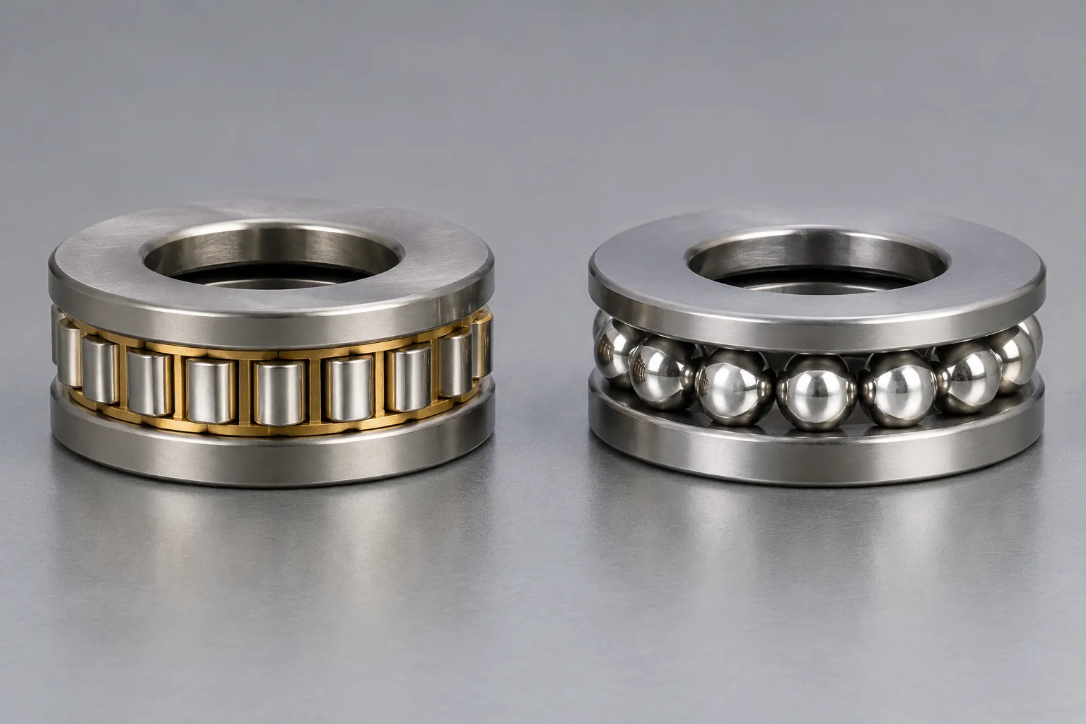
Each roller touches its raceway along a line. This line contact, compared with the point contact of a ball thrust bearing, spreads the load over a wider area. As a result, the bearing can support high axial loads and deliver high axial stiffness while staying axially compact. It is not built to carry radial loads.
Construction and Components
Most single-direction units have three main parts:
- A cage-and-roller assembly that maintains roller spacing and guidance.
- A shaft washer that bears against the shaft-side raceway.
- A housing washer that bears against the housing-side raceway.
In many axial cylindrical roller bearing designs, the housing washer is centered by its outside diameter, while the shaft washer is centered by its inside diameter. These washers and the roller-and-cage assembly can be separated, which helps with mounting, removal, and handling.
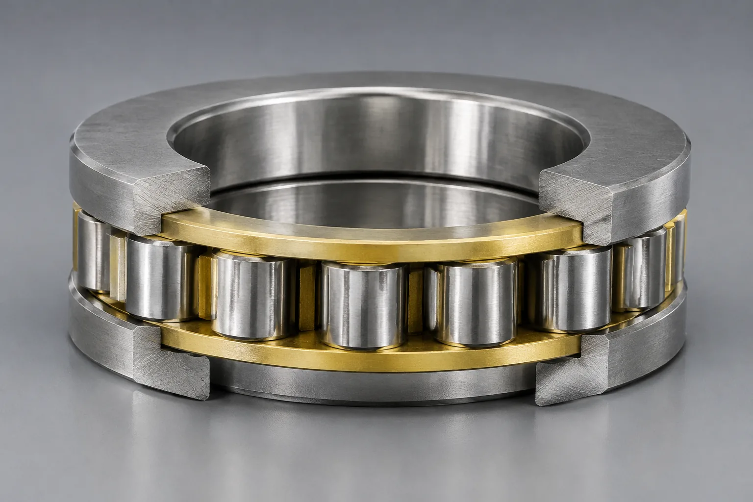
Machined brass is a frequently used cage material; other materials and internal configurations are available for particular duties. The 81152 M example uses a machined brass cage.
How It Carries Load: Axial Only
A cylindrical roller thrust bearing supports axial load only. It is not intended to carry radial load. In the standard single-row version, it handles heavy axial loads and peak loads in one direction but does not fix the shaft in the opposite direction.
Where reverse axial loads exist, select a double-direction bearing or a suitable bearing arrangement, and check the layout against the application drawing and manufacturer data. Radial loads must be carried by a separate radial bearing.
Contact Geometry and Load Capacity
Cylindrical rollers touch the raceways along a line, so the load is spread over a larger contact area than with a ball thrust bearing. That line contact permits higher load capacity and greater axial stiffness than point contact. Key benefits are high axial load capacity, high axial rigidity, and a relatively small axial space requirement.
These bearings are often chosen when a thrust ball bearing cannot provide enough axial load capacity. The examples below show how published ratings differ with size; each value applies only to the listed model and is not a universal limit.
| Example | Boundary dimensions | Basic dynamic axial load rating | Basic static axial load rating | Speed data |
|---|---|---|---|---|
| 81152 M | 260 mm bore x 320 mm outside diameter x 45 mm height | 490 kN | 2,600 kN | 530 r/min reference; 1,100 r/min limiting |
| 81102 TN | 15 mm x 28 mm x 9 mm | 14,400 N | 28,500 N | 13,000 rpm oil limiting |
The 81152 M example also has a net mass of 8.69 kg. Ratings and dimensions depend on bearing size, design, and lubrication, so they must be checked for the exact part.
Speed Limitations and Operating Conditions
Along their length, the rollers experience differential sliding, so cylindrical roller thrust bearings are usually chosen for low or moderate speeds. They are not the first choice for very high speed. Published limits change with lubrication, load, size, cage design, and bearing series.
The 81152 M example lists 530 r/min reference speed and 1,100 r/min limiting speed. The 81102 TN example lists 13,000 rpm with oil lubrication. The low axial section makes the bearing compact, but the speed rating still has to be checked for the application.
Comparison with Thrust Ball Bearings
Cylindrical roller thrust bearings are often selected when a thrust ball bearing lacks sufficient axial capacity. Roller-to-raceway line contact produces greater axial capacity and stiffness than ball-to-raceway point contact. The drawback is reduced speed capability, caused by sliding along the rollers.
| Characteristic | Cylindrical roller thrust bearing | Thrust ball bearing |
|---|---|---|
| Rolling contact | Cylindrical rollers with line contact | Balls with point contact |
| Axial load capacity | High for a compact axial section | Generally lower than a line-contact roller design |
| Axial rigidity | High | Generally lower than a comparable roller thrust bearing |
| Speed suitability | Low-to-moderate speeds | Can be considered where lower loads or very high speed are required |
| Typical choice | When a thrust ball bearing lacks axial capacity | Lower axial loads or high-speed needs |
Common Series, Sizes, and Specifications
Standard series for this bearing type include the 811 and 812 series. One published product line covers bore diameters from 35 mm to 320 mm; this figure describes that product line and is not an industry-wide absolute limit. Availability by size varies among manufacturers and series.
The 81152 M and 81102 TN examples show the range from large to small. The 81152 M has a 260 mm bore, 320 mm outside diameter, and 45 mm height. The 81102 TN has a 15 mm bore, 28 mm outside diameter, and 9 mm height. Check the current series and size against the manufacturer catalog before ordering.
Typical Applications
These bearings are used where high axial capacity, high axial rigidity, low axial installation space, and low-to-moderate speed are required. Typical uses include:
- Machine-tool rotary tables.
- Gearboxes.
- Extruders.
- Injection-molding machinery.
- Mining equipment.
- Steelmaking machinery.
They are often chosen when a thrust ball bearing lacks enough axial capacity. Applications with significant radial loads need a separate radial bearing.
Standards and Specifications
Key ISO references for thrust bearings and rating calculations are listed below. Confirm the current edition before design or procurement.
- ISO 104:2015 sets out boundary dimensions for thrust bearings. Its preferred dimensions for flat-back single- and double-direction bearings cover dimension series 11, 12, 13, 14, 22, 23, and 24. The 4th edition appeared in September 2015 and was confirmed on April 1, 2026; it remains current. The standard applies to thrust bearings in general, not exclusively to cylindrical roller thrust bearings.
- ISO 199:2023 gives GPS (geometrical product specifications) and tolerance values for thrust bearings; it replaced ISO 199:2014.
- ISO 281:2007 deals with dynamic load ratings and rating life. Its basic rating life is based on 90% reliability. It was under revision as of 2026.
- ISO 76:2006 addresses static load ratings and offers static safety factor guidance for heavy-duty applications. It was under revision as of 2026.
Terminology: Cylindrical Roller Thrust Bearing vs. Cylindrical Roller Bearing
A cylindrical roller thrust bearing is not the same as an ordinary cylindrical roller bearing. The thrust design mainly carries axial load; an ordinary cylindrical roller bearing usually carries radial load. In specifications and purchasing documents, use the full term to prevent confusion.
Recognized English names include axial cylindrical roller bearing, cylindrical roller thrust bearing, and thrust cylindrical roller bearing. Manufacturer naming conventions differ, so confirm the exact product description.
When to Choose a Cylindrical Roller Thrust Bearing
Select this type when a thrust ball bearing cannot provide sufficient axial load capacity and the application requires high axial rigidity in a low axial section. Before selection, check these points:
- Confirm that the application applies axial load only; radial loads need a separate bearing.
- Verify the required axial load, speed, required life, lubrication, and available axial space.
- Check dimensions, load ratings, and speed limits against manufacturer data and the applicable ISO standards.
- Use the separable design to simplify mounting and maintenance when handled correctly.
- Do not use the type for very high-speed duties unless the selected bearing is rated for them.
Conclusion
The choice of a cylindrical roller thrust bearing depends on load direction, load magnitude, available axial space, and speed. The type fits high axial loads and high axial rigidity at low-to-moderate speed, especially when a thrust ball bearing lacks capacity. Confirm axial-only loading, provide separate radial support where needed, and verify speed, lubrication, dimensions, and ratings against current manufacturer data and the applicable ISO standards before ordering. The separable washer and cage assembly also helps with mounting and maintenance when handled correctly.
FAQs
Q1: What is a cylindrical roller thrust bearing used for?
A: It carries axial loads in applications such as gearboxes, extruders, machine-tool rotary tables, injection-molding machinery, mining equipment, and steelmaking machinery. It is chosen where high axial capacity and rigidity are needed and a thrust ball bearing is insufficient. It is limited to axial load and low-to-moderate speed.
Q2: Can a cylindrical roller thrust bearing carry radial load?
A: No. The bearing handles axial load only and cannot support radial load. Any radial load needs a separate radial bearing.
Q3: How does it differ from a thrust ball bearing?
A: Cylindrical rollers make line contact, which yields more axial capacity and stiffness than the point contact of a ball thrust bearing. The trade-off is lower speed capability due to sliding along the rollers. Thrust ball bearings may suit lower loads or very high speed.
Q4: What speed can a cylindrical roller thrust bearing handle?
A: Because the rollers slide differentially along their length, the bearing is usually limited to low or moderate speeds. Actual limits depend on size, lubrication, load, and manufacturer ratings. The 81152 M example lists a 530 r/min reference speed and 1,100 r/min limiting speed; the 81102 TN example lists a 13,000 rpm oil limiting speed. Verify speed limits against the specific manufacturer catalog.
Q5: What are common series and standards for cylindrical roller thrust bearings?
A: Common standardized series include 811 and 812. Relevant standards include ISO 104 for boundary dimensions, ISO 199 for GPS and tolerances, ISO 281 for dynamic load ratings and rating life, and ISO 76 for static load ratings. Verify current standard editions before design or procurement.