Quick Answer: Disc springs are conical, washer-shaped spring elements that deflect axially to store energy and apply a defined force in a very short space. A single disc has limited travel but carries high force, and stacking several discs changes force and travel. Selection depends on load, travel, space, guidance and friction, and standardized sizes follow DIN EN 16983.
A disc spring looks like a plain washer until it is loaded. The conical section flattens under axial force, stores elastic energy and returns it when the load is removed. That behavior matters wherever a compact joint, bearing or clamping device must hold a known force without a long spring housing. The sections below cover the geometry, the load-deflection curve, stacking, materials and finishes, selection, installation checks and the failure modes worth watching for.
What Is a Disc Spring?
A disc spring is an annular disc with a conical profile: a center hole, an outer edge, a defined thickness and a cone height between the flat and loaded states. It is made from spring steel and heat treated so that it behaves elastically rather than simply bending.
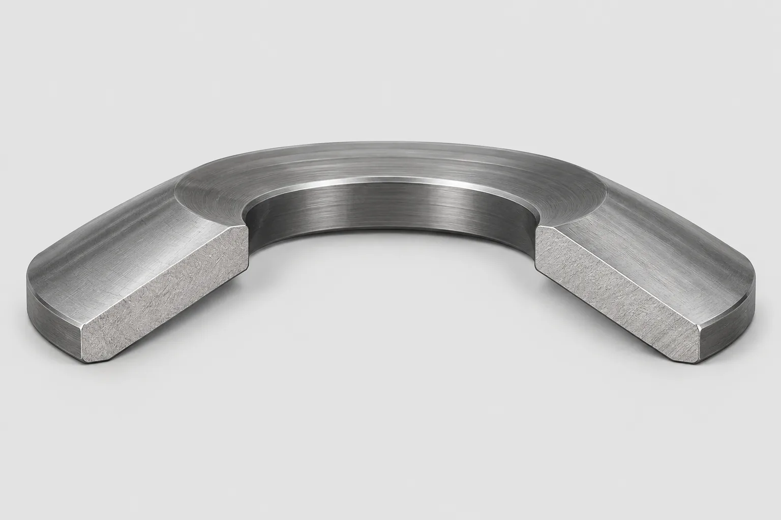
The difference from a flat washer is functional. A flat washer mainly spreads a load and is not designed to deflect in a controlled way. A disc spring is a spring: its force at a given deflection can be calculated, and it can be specified as a preload element in its own right.
Several names describe the same component. Disc spring, Belleville spring, Belleville disc spring and Belleville washer are terminology variants, not different geometries. What does change a part is the drawing or standard it is produced to. Standardized disc springs follow DIN EN 16983, which replaced DIN 2093 and covers dimensions and quality requirements; non-standard parts are made to drawing with agreed dimensions, material and tolerances. When replacing a disc spring, match the drawing or standard reference rather than the name.
How Disc Springs Work
Axial compression pushes the cone toward flat. The material resists that change of shape, so the spring pushes back with an elastic reaction force. The energy is stored as elastic strain in the disc and released when the load is reduced.
Because the geometry changes as the disc flattens, the relationship between force and deflection is not a straight line. A disc spring can deliver a high force within a small axial travel, which is the reason it is used where a coil spring would need far more length. The exact curve depends on outside diameter, inside diameter, thickness, cone height, material and the friction conditions at the loaded edges.
Key Design Parameters and Terminology
Buyers and designers normally work from the same small set of dimensions and performance figures:
- Outside diameter and inside diameter set the annular area and the space the disc needs.
- Material thickness drives force and stress; a small thickness change moves the load noticeably.
- Free height and cone height define how far the disc can deflect before it flattens.
- Flat load and spring rate describe the force at a defined deflection and the stiffness around the working point.
- Working stress at the critical locations decides fatigue behavior in dynamic service.
These parameters interact. Enlarging the outside diameter or increasing thickness raises the force, but it also changes the stress distribution, so a value cannot be adjusted on its own. Dimensional series and stress calculations belong to the applicable standard or to the supplier’s design data, and a critical application should be confirmed by calculation rather than by comparison with a similar-looking part.
Common Materials and Finishes
Disc springs are made from spring steel and hardened and tempered so that they can deflect repeatedly without taking a permanent set. The material choice also affects how the part behaves under corrosion and at elevated stress.
Surface finish has two jobs. It provides corrosion protection, and it influences friction where discs contact each other or their seats. Friction and corrosion are both failure-relevant: corrosion and stress-corrosion cracking can initiate fatigue damage, and unlubricated contact in a stack adds hysteresis and heat.
Specific steel grades, hardness ranges and coating specifications should be taken from the applicable standard or from supplier data for the exact part. The same nominal size can be supplied in more than one material and finish condition, and those differences affect load, life and corrosion resistance.
Load-Deflection Behavior
The force-deflection curve of a disc spring is nonlinear, so stiffness changes as the disc compresses. Near the flat position the force can rise quickly for a small additional travel, which is useful for clamping but demanding for the housing and the guidance.
At certain height-to-thickness ratios, the curve can also include a snap-through or bistable region. Confirm the actual curve for the selected geometry by calculation rather than assuming a monotonic response.
Two operating limits deserve attention at the design stage:
- Deflection beyond roughly 75% of the cone height moves the disc into a steeper part of the curve, where stress becomes strongly nonlinear and fatigue damage can accumulate faster.
- Operation close to full unloading lets the stress at the inner edge reverse each cycle, which shortens fatigue life. Design guidance often calls for a minimum preload in the region of 15%-20% to keep the disc loaded through the cycle.
In a multi-disc stack, friction between mating faces separates the loading and unloading curves. That gap, called hysteresis, is not a defect; it is a real energy loss that changes the force the assembly delivers and generates heat in high-cycle applications.
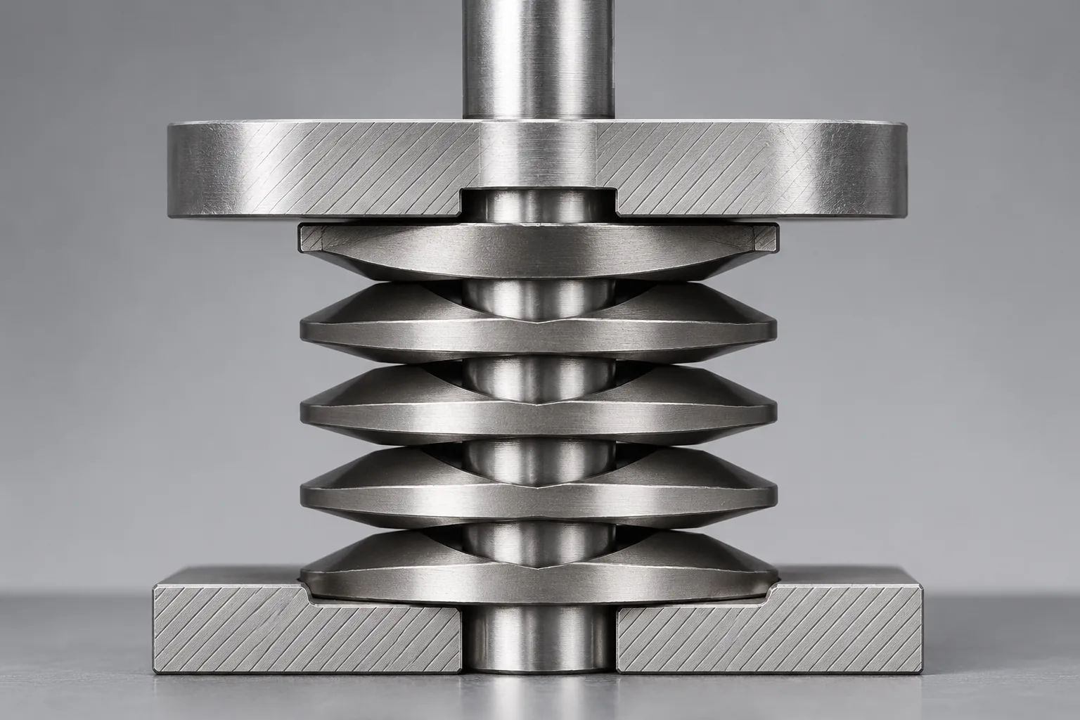
Stacking Configurations
Stacking is how one disc size is adapted to a different force or travel requirement.
| Arrangement | Effect on force | Effect on travel | Practical note |
|---|---|---|---|
| Parallel, same direction | Total force is multiplied by the number of discs | Travel stays close to that of one disc | Friction between mating faces adds hysteresis and heat |
| Series, alternating direction | Force stays close to that of one disc | Travel is added across the stack | Needs reliable guidance to stay concentric |
| Combination | Set by the number of parallel groups | Set by the number of series groups | Used when neither plain arrangement fits the envelope |
Parallel stacks need lubrication and a guiding element so the discs stay aligned; without them, friction and misalignment make the delivered force uneven and can create localized stress. Guiding also limits radial movement, which otherwise lets the discs shift off center under load.
Advantages and Limitations
Disc springs are chosen for a specific combination of strengths:
- High force from a very short axial package.
- A preload that can be calculated and repeated from part to part.
- Workable in compact housings where a coil spring cannot fit.
- Force and travel can be tuned by stacking the same disc.
The limitations follow from the same geometry:
- Travel per disc is small, so a long stroke needs a tall series stack.
- Sensitivity to seat parallelity, guidance and friction.
- Hysteresis and heat in unlubricated parallel stacks.
- Long-term relaxation, fatigue and cracking risk in dynamic service.
Typical Applications
Disc springs appear wherever a defined axial force must be held in a small space:
- Bearing preload in gearboxes, spindles and automotive components.
- Clamping force in clutches, brakes and friction assemblies.
- Valve and seat loading in pumps and compressors.
- Preload of bolted joints and shaft assemblies.
- Overload protection and energy storage in industrial and precision machinery.
The same part can serve very different duties, so load level, cycle count, temperature and corrosion exposure must be confirmed for the actual application rather than assumed from the general category.
How to Select a Disc Spring
- Define the force required at the working position and the force acceptable at the end stops.
- Define the available axial space, the outside and inside diameter limits, and the travel needed.
- Decide between a single disc, a stack and a custom part, using the force and travel rules for parallel and series arrangements.
- Check the stress range and expected cycle count for dynamic duty; static preload and fatigue duty are different design cases.
- Choose material and finish for the environment, including corrosion exposure and lubrication access.
- Confirm the part against the standard series or supplier data, and verify the assembled force by measurement on critical joints.
A standard size is normally the faster route and is easier to replace later. A non-standard geometry is justified when the space, force or fatigue requirement cannot be met by an existing size, and then the drawing and the supporting calculation should be agreed before production.
Installation and Maintenance Considerations
- Keep discs and seats clean and free of burrs; a trapped particle changes the force and creates a stress riser.
- Support the disc on flat, parallel faces and apply the load axially so the cone flattens evenly.
- Guide the stack with a rod or bore that keeps the discs concentric, with clearance for the deflection.
- Lubricate parallel stacks as specified for the application to control friction, hysteresis and wear.
- Inspect periodically for cracks at the critical stress locations, permanent set, loss of installed height and a change in measured force.
No universal calendar-based replacement interval applies to disc springs. Condition-based inspection, and for critical duty a fatigue assessment based on the calculated stresses, is more reliable than a fixed schedule. A disc that has lost height or force should be replaced together with a check of the cause, because a new part will repeat the failure if the deflection range or the preload is wrong.
Disc Springs vs Other Spring Types
The choice between spring types is a comparison of space, force, travel and control.
| Spring type | Axial space | Force for its size | Usable travel | Main limitation |
|---|---|---|---|---|
| Disc spring | Very short | High | Small per disc | Sensitive to seat parallelity, guidance and friction |
| Helical coil spring | Long | Moderate to high | Large | Needs a long housing and guidance to avoid buckling |
| Wave washer or flat washer | Very short | Low | Very small or none | Limited elastic range and limited load control |
Compared with a helical coil spring, a disc spring gives far more force for its axial length, while a coil spring gives far more travel. Compared with a wave washer or a flat washer, a disc spring provides a higher and more controllable elastic load. The practical answer depends on load, travel, space, cost and which factor is fixed by the housing, the joint design or the maintenance access.
Conclusion
Disc springs solve a specific problem: holding a defined axial force in a short space, with a force-deflection curve that can be calculated and repeated. The decisions that matter are the required force and travel, the available space, the stacking arrangement, the material and finish for the environment, and the guidance and lubrication that keep friction predictable.
A workable next step is to write down the working force, the permitted travel, the envelope dimensions and the cycle count, then match that against a standard size before considering a custom disc. Confirm the stress range for dynamic duty, verify the assembled force on the first units, and inspect for cracks, permanent set and height loss during service.
FAQs
Q1: Are disc springs and Belleville springs the same thing?
A: In ordinary usage, yes. Disc spring, Belleville spring, Belleville disc spring and Belleville washer describe the same conical washer-shaped element, and the names differ by region and industry rather than by geometry. What does change the part is the drawing or standard it is made to, so match dimensions, material and tolerances when replacing one instead of relying on the name.
Q2: Can disc springs be stacked to increase force or travel?
A: Yes. Parallel stacking raises the total force while travel stays close to that of a single disc; series stacking adds travel while force stays close to that of one disc; combination stacks set both by the number of groups. Any multi-disc stack needs lubrication and guidance, because friction between faces changes the force the assembly actually delivers.
Q3: How is the load of a disc spring stack calculated?
A: From the single-disc characteristic plus the arrangement. Standardized calculation methods relate force and stress to outside diameter, inside diameter, thickness and cone height, then parallel discs multiply force and series discs add deflection. Seating, tolerances and friction mean measured output differs from the calculated value, so critical assemblies should be verified by measurement.
Q4: What material are disc springs made from?
A: Spring steel, hardened and tempered to give elastic behavior without permanent set. The surface finish supplies corrosion resistance and modifies friction, which matters in humid, chemical or high-cycle service because corrosion and stress-corrosion cracking can start fatigue failure. Grades, hardness ranges and coating specifications belong to the applicable standard or the supplier’s data for the exact part.
Q5: Do disc springs need a fixed replacement schedule?
A: No universal calendar interval applies. Condition-based inspection is more dependable: look for cracks, permanent set, loss of installed height and a change in force-deflection behavior. Fatigue life depends on stress range, deflection and cycle count, so discs in critical dynamic duty are assessed from the calculated stresses at the critical locations rather than from an hours-based rule.
Q6: Why has a disc spring lost its preload?
A: Common reasons are relaxation after long service, fatigue cracking, excessive deflection, insufficient preload that lets the disc unload fully, and friction or heat in an unlubricated stack. Check the deflection range and the stack condition before fitting a replacement, because a new disc will repeat the same failure if the cause sits in the design rather than in the part.