Quick Answer: Gear backlash is the small clearance between meshing teeth when their working flanks are in contact, measured as linear clearance at the pitch circle or as angular lost motion with one gear held fixed. It leaves room for lubricant film, thermal expansion, shaft deflection, and manufacturing tolerances. Too little backlash can bind, score, and overheat the teeth; too much produces impact, noise, and positioning error in reversing drives. Acceptable values are application-specific, so check the gearbox specification.
Gear backlash sits behind several problems that owners blame on bearings, lubrication, or alignment. The same amount of lost motion can be normal for one drive and excessive for another, because the limit belongs to the specific gear pair and its duty. Reading backlash correctly means knowing what is being measured, under which condition, and against which specification.
What Is Gear Backlash?
Gear backlash is the circumferential or angular lost motion between two meshing gears when their working flanks are in contact and the drive is at rest or lightly loaded. In practical terms, it is the small rotation one gear can make before its teeth touch the opposite flank of the mating gear.
Backlash is not a synonym for bearing clearance, center distance, or tooth clearance. Bearing clearance is internal play inside the bearing. Center distance sets how deeply the teeth engage. Tooth clearance, sometimes called root clearance, is the gap between a tooth tip and the root of the mating tooth. Backlash is measured at the flanks where the teeth actually transmit load.
The value can be expressed in two ways. Linear backlash is a clearance measured at the pitch circle, while angular backlash is the rotation of one member measured while the other is held fixed. The two expressions describe the same condition but are not interchangeable without the pitch radius. Where a drawing uses formal symbols, confirm the notation against the applicable AGMA, ISO, or accepted gear handbook before comparing values. The definition applies to both external and internal gear pairs, although the measurement plane and the accepted convention differ by gear type.
Why Gear Backlash Is Necessary
A controlled amount of backlash keeps a gear drive from running metal-to-metal. It accommodates:
- the thickness of the lubricant film between the flanks
- thermal expansion of gears, shafts, and housing as the drive warms up
- shaft and housing deflection under load
- manufacturing tolerances in tooth thickness and center distance
- assembly variation introduced during build or repair
Without that margin, the teeth can bind, carry excessive preload, and overheat. The amount required depends on load direction, reversing duty, positioning accuracy, operating temperature, and the lubrication method.
Zero-backlash, anti-backlash, and spring-loaded gear systems are engineered differently and follow their own manufacturer instructions. General backlash guidance should not be applied to those designs.
What Causes Gear Backlash
Measured backlash is the result of a tolerance stack, not only of tooth thickness. The main contributors are:
- tooth thickness variation within the manufacturing tolerance
- center distance error between the two shafts
- profile and lead errors on the flanks
- runout and mounting eccentricity of gears or shafts
- bearing clearance and bearing seat condition
- shaft deflection under operating load
- thermal expansion at working temperature
- wear of the flanks after service
The reading can change after assembly, after break-in, after thermal cycling, and as wear develops. The relative contribution of each factor varies with gear type, housing design, lubrication, load, and temperature.
Not every backlash problem starts in the gears. Bearing clearance, housing alignment, and shaft deflection have to be checked before a gear set is condemned.
Effects of Too Much or Too Little Backlash
Both directions of error damage a drive, but in different ways.
Insufficient backlash closes the lubrication gap and raises contact stress:
- tooth binding and metal contact
- scoring and scuffing of the flanks
- overheating and increased friction loss
- risk of seizure in severe cases
Excessive backlash removes the control the mesh provides:
- lost motion between input and output
- impact loading each time the drive reverses
- noise and vibration
- positioning error in indexing or servo axes
- accelerated wear in reversing duty
These conditions show up as abnormal noise, local heat, vibration, and inconsistent motion. A unidirectional, lightly loaded drive can tolerate more backlash than a reversing, indexing, or precision positioning drive. The acceptable balance also depends on whether the axis is servo-controlled or high-speed.
How to Measure Gear Backlash
Backlash measurement is a controlled check of lost motion between meshing gears. A usable record states the temperature, the gear position, the load condition, and the measurement plane, because a reading without those details cannot be judged against a limit.
Measure at the temperature and condition the equipment manufacturer specifies. If the drive cannot be brought to that condition, state the actual condition clearly alongside the reading. Enclosed gearboxes may need access ports, special fixtures, or a dedicated service procedure, so no single method fits every unit.
Preparing for Backlash Measurement
Lock or hold one gear or shaft stationary, then rotate the mating member through the backlash range only. Mark reference positions so repeated readings land in the same place, and use a rigid indicator mounting so stand movement is not read as gear movement. Record ambient or oil temperature and note whether the gearbox is unloaded, loaded, or at operating temperature. The exact preparation depends on gearbox accessibility, shaft arrangement, and the manufacturer service instructions.
Dial Indicator Method
Place the indicator plunger normal to the tooth flank, or on a defined reference point at the pitch circle where access allows. Rock the mating gear gently against one flank and then the other, and record the total indicator movement as backlash. Repeat at several positions around the gear to expose variation from runout or eccentricity.
The indicator must be rigidly mounted and aligned with the direction being measured, and its resolution should be fine enough to resolve the specification limit with confidence. Readings taken through a flexible bracket or at an angle to the true direction distort the result. Take repeat readings at the same position and confirm they agree before recording the result; a changing reading usually means the mounting or the reference mark is moving.
Feeler Gauge and Lead Wire Method
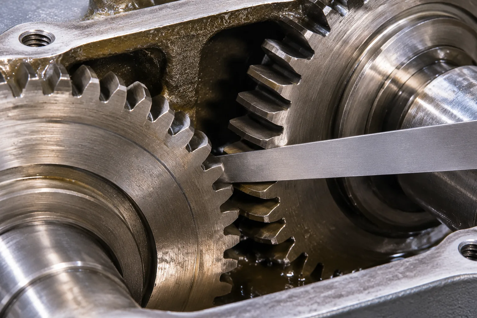
A feeler gauge can be inserted between accessible tooth flanks on open gearing, and a lead wire or soft wire can be crushed between the flanks where clearance is inferred from the crushed thickness. Both methods depend on reliable placement, so they suit open gears with clear access and geometry that lets the gauge sit on the true contact zone. Use them only where the maintenance procedure or manufacturer accepts the method. They are a poor choice for enclosed, lubricated, or precision gear systems.
Angular Backlash Measurement
Hold one shaft fixed and measure the angular rotation of the mating shaft through the backlash range. Convert to linear backlash at the pitch radius when the specification is written that way:
Linear backlash = angular backlash in radians x pitch radius
State the radius and the convention used, and use the pitch radius or the radius the gear manufacturer specifies. Mixing angular and linear conventions is a common source of false pass or false fail results.
Typical Gear Backlash Values and Standards
There is no universal acceptable backlash value for all gears. A figure that is correct for one drive may be far outside the limit for another, because the specification depends on module or diametral pitch, gear type, pitch line velocity, application, manufacturing quality class, and operating temperature.
Take the limit from the gearbox or gear manufacturer data for the exact unit, or from the applicable AGMA, ISO, or other gear standard the design was built to. A complete specification states the unit of measurement, the measurement plane, the reference temperature, and the gear position where the check is made. Without those four items, a number cannot be compared with a reading taken on the shop floor.
Do not carry values between applications. Automotive, robotics, and industrial gearbox figures are set on different duty assumptions, and interchanging them without confirming the basis can pass a drive that is out of limits.
Design and Assembly Considerations
Final backlash is fixed by the tolerance stack chosen at design stage and realized during assembly. Center distance tolerance, tooth thickness tolerance, bearing clearance, housing alignment, and shaft deflection all shift the result, and the stack should be verified during assembly rather than assumed from the drawing.
Thermal expansion can either reduce or increase backlash, depending on the materials, the temperature rise, and the housing design. A drive that measures correctly cold can close up at operating temperature when the housing expands less than the gear and shaft train. Specify backlash at a defined reference condition and check the running condition separately.
Design checks should use the actual operating temperature, the real material pair, and the housing constraints of the application. Use the actual material coefficients and the measured or specified temperature rise in that check rather than a generic allowance. High-temperature and cryogenic applications usually need dedicated allowances rather than general guidance.
Adjusting and Controlling Gear Backlash
Correction depends on how the drive is built. Common approaches are:
- shimming a bearing housing or gearbox mounting face
- moving an eccentric bearing housing to reset center distance
- using adjustable motor or gearbox mounts
- replacing worn gears, bearings, or seats that created the excess play
Any adjustment must preserve gear alignment and the bearing preload or clearance the design requires. Closing backlash by forcing the mesh tighter can overload the bearings and the teeth. Re-measure backlash after adjustment, and again after a short run-in period where the procedure calls for it, because the reading can settle once the drive has run under load.
Field modifications that change housing geometry or the bearing arrangement should not be attempted without engineering approval.
Gear Backlash by Gear Type
Measurement and specification conventions differ across gear types, and the measurement plane has to be stated for each one.
- Spur gears are normally checked in the plane of rotation at the pitch circle.
- Helical gears carry the same principle, but the helix angle adds an axial component that must be accounted for in the setup.
- Bevel gears are usually checked normal to the tooth flank near the defined reference position on the face width, and the reading is sensitive to where along the face it is taken.
- Worm gears may be defined as angular free play at the output or as flank clearance, so the convention must be confirmed before any comparison.
Confirm the detailed convention in the applicable gear standard or handbook before comparing a reading with a limit. Values from different gear types should not be compared unless the same convention, plane, and reference position are confirmed.
Symptoms of Incorrect Backlash and Maintenance Checks
Observable signs include abnormal gear noise, vibration, local overheating, metallic debris in the lubricant, visible lost motion at the output, and inconsistent positioning. These symptoms overlap with bearing, lubrication, alignment, and tooth wear problems, so backlash should be checked as part of a wider inspection rather than treated as the single cause.
Periodic backlash measurement against a baseline or the manufacturer limit is the reliable way to track change. Pair it with lubricant inspection and a tooth contact pattern check, and record the temperature and position of each reading so later comparisons mean something. Noise or vibration alone does not confirm incorrect backlash; measurement and inspection do.
Conclusion
Gear backlash is a controlled clearance, not a defect, and its correct value belongs to the specific gear pair and duty rather than to a general table. Too little clearance binds, scores, and overheats the flanks; too much produces impact, noise, lost motion, and positioning error. Measure at the stated temperature and plane, repeat around the gear to expose runout, and compare the reading with the gear or gearbox manufacturer specification. When a reading falls outside the limit, correct center distance through the approved adjustment points, keep alignment and bearing preload intact, and re-measure after run-in.
FAQs
Q1: What is gear backlash?
A: Gear backlash is the clearance between the non-working flanks of a meshing pair when the working flanks are in contact, expressed either as linear clearance at the pitch circle or as angular rotation of one gear with the other held fixed. It is a flank measurement and should not be confused with bearing clearance or root clearance. The What Is Gear Backlash? section explains the distinction from bearing clearance and root clearance.
Q2: What is acceptable gear backlash?
A: The acceptable value is the one stated for that specific gearbox or gear set by its manufacturer or by the standard the design was built to. A usable limit states the unit, measurement plane, reference temperature, and gear position, so a reading taken under other conditions cannot be judged against it. See Typical Gear Backlash Values and Standards for the four specification details.
Q3: How do you adjust gear backlash?
A: Adjustment is normally made by shimming a housing or mounting face, repositioning an eccentric bearing housing, using adjustable mounts, or replacing worn gears and bearings. Alignment and bearing preload must stay within specification, and backlash should be re-measured after adjustment and after run-in. See Adjusting and Controlling Gear Backlash for the approved adjustment points.
Q4: Can excessive backlash come from something other than worn gears?
A: Yes. Bearing clearance, housing alignment, shaft deflection, mounting eccentricity, and the original tolerance stack can all add lost motion, and the reading also shifts with temperature. Inspect those items before replacing a gear set that may still be serviceable. See What Causes Gear Backlash for the tolerance stack and inspection points.