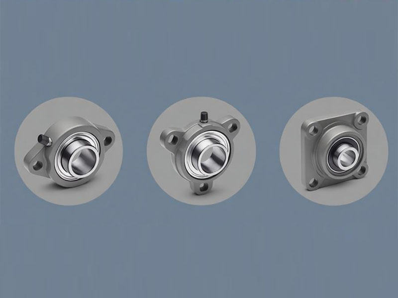
Quick Answer: A flange mounted bearing is a pre-assembled unit with the shaft axis perpendicular to the mounting surface. Common housing styles include 2-bolt (FL), 3-bolt (FB), and 4-bolt (F, FA, FC, FS) configurations. These units accept insert ball bearings from the UC, SA, SB, UK, UE, and UEL series, using set screw, adapter sleeve, or eccentric collar locking. For loads above 5 kN or significant vibration, 4-bolt housings are recommended. For loads under 3 kN in spaces narrower than 50 mm, 2-bolt FL types offer a practical alternative.
A flange mounted bearing is a ready-to-install assembly comprising a flanged housing and an insert bearing. The defining feature is the shaft orientation: the shaft extends outward at a right angle from the mounting face. This perpendicular arrangement makes flange units particularly suitable for side-wall mounting and applications where the shaft must pass through a frame or panel.
This orientation marks the primary difference from pillow block bearings. In pillow blocks, the shaft sits parallel to the mounting surface and the unit rests on a horizontal base. Flange bearings, by contrast, bolt directly to vertical surfaces or machine frames, with the shaft projecting outward.
Factory-sealed and pre-greased, these units arrive ready for immediate use. Replacing a worn unit is straightforward: unbolt the old assembly and bolt in a replacement. No pressing or heating is required. Beyond installation convenience, flange bearings help protect the shaft from bending and deflection, which can lead to vibration, misalignment, or premature component wear. Typical applications span conveyor systems, fans, agricultural machinery, automotive assemblies, and general industrial equipment.
Housing Types: 2-Bolt, 3-Bolt, and 4-Bolt Flange Bearings
Flange bearing housings fall into distinct categories based on bolt count and overall geometry. The choice among these styles depends on available space, load requirements, and mounting surface characteristics. The following table summarizes the six main housing types:
| Code | Name | Bolt Holes | Housing Shape | Key Characteristics |
|---|---|---|---|---|
| F | Square 4-bolt flange | 4 | Square | Most widely used style; straightforward design; mounts easily on side walls |
| FA | Hanging flange housing | 4 | Square | Manufacturer-specific code; designed for suspended or overhead mounting |
| FB | Flange bracket | 3 | Triangular or offset | 3-bolt pattern with offset holes; compact footprint for light-duty wall mounting |
| FC | Piloted flange cartridge | 4 | Round with pilot boss | Includes a circular locating boss on the back face; ensures precise positioning |
| FL | Diamond 2-bolt flange | 2 | Diamond or oval | Saves space where 4-bolt square housings cannot fit |
| FS | Square flange | 4 | Square | Similar to F type; manufacturer-specific variant |
F Type – Square 4-Bolt Flange
The F type stands as the most common flange bearing housing in industrial settings. Its square body and four mounting bolts provide balanced support across the mounting surface. Installers typically attach this style to vertical machine frames or side walls. The design’s simplicity and the even distribution of clamping force make it the preferred choice for most general-purpose installations.
FA Type – Hanging Flange Housing
The FA designation appears mainly in specific manufacturer product lines. This style, sometimes labeled as a hanging seat, supports configurations where the bearing assembly suspends from an overhead support structure. While the FA housing shares the four-bolt layout of the F type, its mounting geometry suits inverted or hanging positions rather than standard side-wall attachment. Engineers encounter this variant less frequently and should consult manufacturer specifications for exact dimensions and load ratings.
FB Type – 3-Bolt Flange Bracket
The FB type carries a triangular or offset housing with three bolt holes. The three-point mounting scheme delivers stable support while maintaining a smaller overall footprint than 4-bolt designs. Depending on the manufacturer, the bolt holes may be arranged radially at 120-degree intervals or positioned on a triangular flange set off from the bearing centerline. This style suits light-duty wall-mount applications where space is constrained but three attachment points provide adequate rigidity.
FC Type – Piloted Flange Cartridge
The FC type distinguishes itself with a circular pilot boss protruding from the back of the housing. This boss registers into a matching hole machined into the equipment frame. The piloting feature guarantees accurate radial positioning and consistent shaft alignment – essential where even slight misalignment would shorten bearing life significantly. Engineers specify FC units when installation precision is a primary requirement.
FL Type – Diamond 2-Bolt Flange
The FL type presents a diamond or oval housing with two bolt holes positioned on opposite sides of the bearing axis. A line connecting the two bolt hole centers passes directly through the shaft centerline. This compact configuration serves transmission components and narrow machinery frames where 4-bolt square housings cannot fit. Two-bolt designs work well when loads remain below 3 kN and available width stays under 50 mm. However, applications with strong vibration or heavy axial thrust call for more robust 4-bolt housings, as the thinner ears of 2-bolt castings are more prone to cracking under excessive bending moments.
FS Type – Square Flange
The FS type resembles the F type in appearance: a square body with four bolt holes. The distinction between F and FS varies by manufacturer. Some brands use FS to denote a convex square seat, others to indicate a particular material grade or dimensional standard. Both serve identical side-wall mounting functions. When choosing between F and FS, the correct approach is to check the specific dimensions and tolerances in the manufacturer’s catalog rather than relying on the code alone.
Insert Bearing Types: UC, SA, SB, UK, UE, UEL Series
The bearing element inside a flange housing is formally known as an insert bearing or radial insert ball bearing. This component belongs to the deep groove ball bearing family and carries a spherical outer ring surface. This curved outer surface interfaces with the concave spherical bore inside the housing, enabling automatic self-alignment. This self-aligning capability compensates for minor shaft deflection and initial mounting errors, preventing stress concentrations that would otherwise reduce bearing service life.
A critical point of clarification: all conventional insert bearings – the UC, SA, SB, UK, UE, and UEL series – are ball bearings. Products containing roller elements, needle rollers, or plain sliding surfaces do not fall within the standard insert bearing definition for mounted units.
Manufacturers classify insert bearings primarily by their shaft locking mechanism. Three methods dominate the market:
Set Screw Locking – UC, SA, SB Series
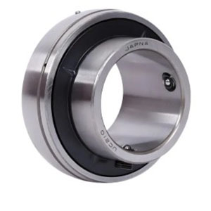
Set screw locking represents the simplest and most common shaft attachment approach. Two set screws (also called grub screws) sit on the inner ring, typically spaced 120 degrees apart. Turning these screws inward drives them against the shaft, securing the bearing firmly in position. This method delivers reliable holding power for the majority of standard industrial applications.
| Series | Description | Key Feature |
|---|---|---|
| UC | Wide inner ring with set screws | Most common general-purpose type; supports radial loads and axial loads up to 20% of the dynamic load rating |
| SA | Narrow inner ring, imperial series | Reduced axial width; fits inch-measured shaft diameters |
| SB | Narrow inner ring, metric series | Reduced axial width; fits millimeter-measured shaft diameters |
UC bearings incorporate an extended inner ring housing two set screws. This series sees widespread use in mining, metal processing, bulk material handling, and other demanding industrial environments.
SA and SB bearings carry narrower inner rings, consuming less axial space. The SA series suits imperial shaft sizes; the SB series matches metric dimensions. Designers specify these narrow types when the available axial installation length is limited.
Adapter Sleeve Locking – UK Series
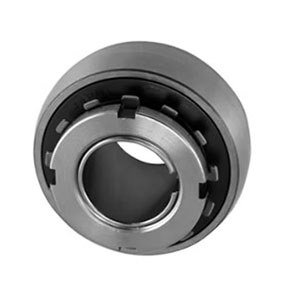
UK bearings feature a tapered bore with a standard 1:12 taper ratio. This tapered bore prevents direct mounting onto a plain cylindrical shaft. Instead, the assembly requires an adapter sleeve that slides over the shaft. The UK bearing then mounts over the sleeve, and a locknut tightens the assembly to secure everything in place.
| Series | Description | Key Feature |
|---|---|---|
| UK | Tapered bore with adapter sleeve | 1:12 taper; supports higher loads than UC bearings of matching bore size; offers superior concentricity and rotational precision |
UK bearings typically handle heavier loads than UC bearings with the same bore diameter. The adapter sleeve approach provides excellent concentricity between shaft and bearing, making it particularly valuable in applications characterized by vibration, shock loads, or demanding rotational accuracy requirements. UK units also work well with plain (non-keyed) shafts and installations that require periodic bearing replacement, since the sleeve design simplifies removal.
Eccentric Collar Locking – UE, UEL Series
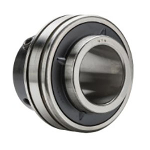
Eccentric collar locking employs a collar with an offset center bore. Rotating this collar relative to the bearing inner ring creates a wedging action that clamps the assembly onto the shaft. The eccentric sleeve’s tightening direction should align with the shaft’s rotation during operation to prevent loosening.
| Series | Description | Key Feature |
|---|---|---|
| UE | Eccentric collar locking | Standard design; generates greater clamping force than set screw methods |
| UEL | Eccentric collar with extended inner ring | Additional inner ring length; delivers higher axial locking torque; suited for vibration and impact conditions |
Eccentric collar locking produces higher clamping forces than set screw arrangements and withstands substantial axial loads. This characteristic makes UE and UEL bearings particularly effective in agricultural equipment and machinery subject to continuous vibration and shock forces. The UEL variant’s extended inner ring provides extra axial gripping power, making it the stronger choice for demanding operating conditions.
Selection Factors and Housing Materials
Choosing the correct flange mounted bearing requires weighing multiple application parameters. The six factors below provide a systematic framework for making the right selection:
1. Shaft Diameter
Shaft dill damage the shaft surface; oversized bores allow fretting (surface damage from microscopic relative motion) and eventual failure.iameter sets the required bearing bore size. Standard flange units are manufactured with bore diameters beginning at 12 mm and increasing in both metric and imperial increments. Match the bore exactly to the shaft – undersized bores w
2. Load Magnitude and Direction
Every flange bearing must carry two load components: radial loads acting perpendicular to the shaft and axial loads acting along the shaft axis. Application engineers should determine both the magnitude and the direction of each load component.
- Loads above 5 kN or high-vibration scenarios demand 4-bolt housings (F, FC, or FS) for maximum rigidity.
- Loads below 3 kN in tight spaces (less than 50 mm available width) may allow 2-bolt FL types.
- Intermediate loads from 3 kN to 5 kN find a suitable balance in 3-bolt FB units.
3. Physical Space Constraints
The available mounting area determines which housing geometry fits.
- Restricted axial or radial space points toward FL (2-bolt diamond) as the most compact option.
- Moderate space with a need for better stability suggests FB (3-bolt triangular) as an intermediate solution.
- Ample space with a requirement for maximum rigidity indicates F, FC, or FS (4-bolt square or round).
4. Positioning Accuracy Demands
Applications that demand precise shaft positioning should specify FC type with the piloted boss. This circular pilot locks into a matching hole in the frame, guaranteeing accurate radial placement and consistent alignment. For less demanding applications, F, FL, and FS types without pilot bosses deliver adequate accuracy at lower cost.
5. Locking Mechanism Choice
Matching the locking method to shaft type and operating conditions:
- Set screw (UC/SA/SB): General service with keyed shafts. Easy installation and broad availability.
- Adapter sleeve (UK): Plain shafts, heavy loads, vibration, and situations requiring frequent disassembly.
- Eccentric collar (UE/UEL): Vibration, impact, and agricultural environments. Holds against axial forces more effectively.
6. Environmental Conditions
Temperature extremes, moisture, chemical exposure, and contamination all influence material selection.
Common housing materials and their recommended uses:
| Material | Key Characteristics | Typical Applications |
|---|---|---|
| Gray cast iron (ASTM A48 Class 30) | Cost-effective; good strength and vibration damping | General industrial use; most common selection |
| Stainless steel | Corrosion resistance | Food processing, marine, chemical plants |
| Sheet steel | Lightweight; economical | Light-duty and cost-sensitive projects |
| Zinc die casting | Lightweight; corrosion resistant | Moderate-duty applications |
| Plastic (PBT) | Non-corrosive; maintenance-free | Specialized non-metallic requirements |
Cast iron remains the default choice for most flange bearing installations. Stainless steel becomes necessary when the unit faces regular washdown, moisture exposure, or aggressive chemicals.
Typical Applications
Flange mounted bearings support essential functions in diverse industries:
- Conveyor systems: Drive shaft support on belt conveyors, roller conveyors, and material handling lines
- Fans and blowers: Industrial exhaust fans, ventilation systems, and air handling equipment
- Agricultural machinery: Tractors, harvesters, balers, and field equipment operating in dusty, high-impact conditions
- Automotive: Vehicle components requiring high-speed rotation and substantial load support
- Industrial manufacturing: Pumps, packaging lines, and mechanical drive assemblies
- HVAC systems: Heating, cooling, and ventilation equipment requiring long service life with minimal maintenance
Conclusion
Flange mounted bearings deliver a convenient, pre-assembled solution for applications requiring shaft installation perpendicular to the mounting surface. Effective selection starts with knowing the six housing styles: F (square 4-bolt, the most common), FA (hanging flange, manufacturer-specific), FB (3-bolt bracket, compact), FC (piloted flange, precision-aligned), FL (2-bolt diamond, space-saving), and FS (square flange, manufacturer-specific).
Selecting the right insert bearing depends heavily on the locking mechanism. Set screw designs (UC, SA, SB) cover general-purpose needs. Adapter sleeve units (UK) manage heavy loads and vibration on plain shafts. Eccentric collar types (UE, UEL) deliver maximum axial holding force for agricultural and impact-heavy applications.
A disciplined selection process weighs six considerations: shaft diameter, load type and magnitude, physical space, positioning accuracy, locking method, and environmental conditions. As a practical reference: loads over 5 kN or vibration-prone applications call for 4-bolt housings; loads under 3 kN in confined spaces under 50 mm width point toward 2-bolt FL units.
DUHUI Bearing, established in 2003, manufactures automotive bearing solutions including flange mounted bearing units. With over 20 years of industry experience and more than 4,000 auto parts models, DUHUI supplies bearings to customers in global markets, providing reliable specifications and consistent product quality.
FAQs
Q1: What distinguishes a flange mounted bearing from a pillow block bearing?
A: In flange mounted bearings, the shaft axis stands perpendicular to the mounting face. In pillow blocks, the shaft axis lies parallel to the mounting face. Flange bearings attach to side walls or vertical surfaces; pillow blocks mount on horizontal bases.
Q2: What insert bearing series are available and what locking methods do they use?
A: Set screw locking covers UC (wide inner ring), SA (imperial narrow), and SB (metric narrow). Adapter sleeve locking applies to UK (tapered bore, 1:12 taper). Eccentric collar locking covers UE (standard) and UEL (extended inner ring).
Q3: How do UC and SA/SB series differ?
A: UC uses a wide inner ring and supports axial loads up to 20% of its dynamic rating. SA and SB use narrow inner rings for compact axial dimensions. SA fits imperial shaft sizes; SB fits metric.
Q4: Why does the UK series require an adapter sleeve?
A: UK bearings carry a 1:12 tapered bore that cannot mount directly to a straight shaft. The adapter sleeve fills the gap between the tapered bore and the shaft, with a locknut securing the assembly. This design provides excellent centering and vibration tolerance.
Q5: What differentiates UE from UEL?
A: Both use eccentric collar locking. UEL carries an extended inner ring that generates higher axial locking torque than UE, making it more suitable for severe vibration and impact service.
Q6: How do I choose among 2-bolt, 3-bolt, and 4-bolt housings?
A: Choose 4-bolt (F/FC/FS) for loads over 5 kN or high vibration. Choose 3-bolt (FB) for loads in the 3-5 kN range. Choose 2-bolt (FL) for loads under 3 kN with installation space under 50 mm width.
Q7: What does the term “piloted” mean in FC flange bearings?
A: “Piloted” indicates that the housing back face includes a circular boss that registers into a mating hole in the equipment frame. This pilot ensures accurate radial positioning and consistent shaft alignment.
Q8: Do flange mounted bearings come pre-lubricated?
A: Yes. Standard flange units leave the factory pre-greased and sealed, requiring no additional lubrication before they go into service.
Q9: What materials are available for flange bearing housings?
A: Gray cast iron (ASTM A48 Class 30) is the standard material. Stainless steel handles corrosive environments. Sheet steel offers a lightweight, economical alternative. Zinc die casting and plastic PBT serve specialized applications.
Q10: What are the load guidelines for selecting 2-bolt versus 4-bolt flange bearings?
A: Use 2-bolt FL units for loads under 3 kN and installation width under 50 mm. Use 4-bolt F/FC/FS units for loads above 5 kN or high-vibration applications. For loads between 3 and 5 kN, 3-bolt FB units provide an intermediate solution.
References
- GlobalSpec Engineering360: Flange Bearings Selection Guide
- Lily Bearing: Flange Bearing Sizes and Types
- HK Royal: UC Series Insert Bearings Specifications
- ISO 15: Rolling Bearings – Radial Bearings – Boundary Dimensions
- ISO 76: Rolling Bearings – Static Load Ratings