Quick Answer: What Is a Hydraulic Release Bearing?
A hydraulic release bearing (also called a hydraulic throw-out bearing or concentric slave cylinder) is a single component that replaces the traditional release bearing and external slave cylinder.
How it works: When you press the clutch pedal, hydraulic fluid pushes a piston inside the bearing. The piston moves the bearing forward against the pressure plate, disengaging the clutch.
Key facts:
- No external clutch fork or slave cylinder—saves space under the hood.
- Lighter pedal feel than mechanical linkages.
- Most aftermarket HRBs require a 0.150–0.200 inch (3.8–5.0 mm) air gap during installation to compensate for clutch disc wear.
A hydraulic release bearing—also referred to as a hydraulic throw-out bearing or concentric slave cylinder (CSC)—is a clutch actuation component that replaces the traditional mechanical release bearing and Themes 0external slave cylinder. Understanding how a hydraulic release bearing works helps diagnose common clutch disengagement issues such as heavy pedal effort, inconsistent release, or limited space under the hood. This article explains the definition, core components, operating principle, advantages, types, maintenance, failure symptoms, and selection criteria for hydraulic release bearings.
Definition of a Hydraulic Release Bearing
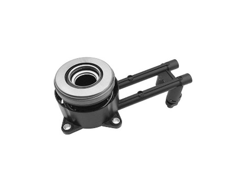
A hydraulic release bearing (HRB) is a device that both applies force to the pressure plate diaphragm spring and contains the hydraulic actuation mechanism in one assembly. It is mounted concentrically around the transmission input shaft, inside the bellhousing. In the automotive aftermarket, it is also called a hydraulic throw-out bearing (HTOB) or, particularly in original equipment contexts, a concentric slave cylinder (CSC). The term “concentric” indicates alignment with the input shaft axis, unlike an external slave cylinder and clutch fork which are offset.
The practical importance of an HRB lies in its ability to deliver smoother, more reliable clutch disengagement across a wide range of vehicles—from daily drivers to track-oriented performance cars and engine-swapped projects. By eliminating the clutch fork, pivot ball, and external slave cylinder, the system becomes simpler and more direct.
The underlying physics is Pascal’s law: pressure applied to a confined fluid is transmitted undiminished. When the driver depresses the clutch pedal, the master cylinder converts mechanical force into hydraulic pressure. This pressure travels via a hose to the HRB, where it acts on a piston. The piston then pushes the bearing forward against the pressure plate’s diaphragm spring, releasing the clutch.
Core Components of a Hydraulic Release Bearing
A hydraulic release bearing consists of several precision-manufactured parts, each with a specific function.
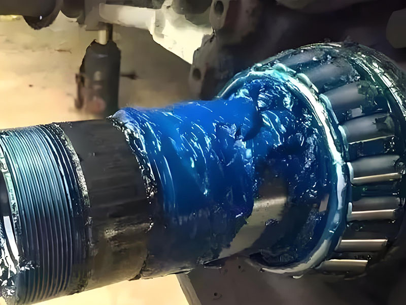
Bearing assembly (inner race, rolling elements, outer race): This rotating part contacts the pressure plate diaphragm spring fingers. It contains precision balls or rollers and must withstand high axial loads and speeds, often exceeding engine RPM. The housing is typically steel or engineered polymer to resist wear and heat.
Hydraulic cylinder and piston: This is the actuator. The cylinder is a machined housing that contains a piston. When hydraulic fluid enters the cylinder, it pushes the piston, which in turn moves the entire bearing assembly forward along the transmission input shaft sleeve. The piston stroke determines bearing travel, directly affecting clutch disengagement.
Sealing system: Seals—usually elastomeric rings such as O-rings or custom-molded profiles—prevent hydraulic fluid from leaking past the piston. These seals must remain flexible and intact under temperatures that can exceed 150°C (300°F) inside the bellhousing. Seal failure is a primary cause of HRB malfunction, as fluid leakage reduces hydraulic pressure and may contaminate the clutch disc.
How a Hydraulic Release Bearing Works
The operational sequence of an HRB-equipped clutch system follows a clear cause-and-effect chain.
Force transmission path:
- Driver presses the clutch pedal.
- The clutch master cylinder converts pedal motion into hydraulic pressure.
- Pressurized fluid (DOT 3 or DOT 4 brake fluid) travels through a hose to the HRB.
- Fluid enters the HRB’s cylinder and acts on the piston face.
- The piston moves forward, carrying the bearing housing.
- The bearing contacts the pressure plate diaphragm spring fingers.
- The diaphragm spring is compressed, pulling the pressure plate away from the clutch disc.
- The clutch disc is no longer clamped, interrupting torque transmission.
Return mechanism: Most HRBs do not have an active return spring. When the driver releases the clutch pedal, hydraulic pressure drops. The diaphragm spring pushes back against the bearing. This reaction force retracts the bearing and piston. In many installations, the bearing remains in light, constant contact with the diaphragm fingers—a normal condition known as “constant-contact” design. It does not accelerate wear if the system is properly set up.
Air gap requirement: During installation, an air gap must be present between the bearing face and the pressure plate fingers when the clutch is fully engaged. For many aftermarket HRBs—such as those used in performance and racing applications—the specified air gap is typically 0.150 to 0.200 inches (3.8 to 5.0 mm). This gap is not an error; it is a design allowance for clutch disc wear. As the friction disc wears thinner over thousands of cycles, the diaphragm spring fingers effectively move closer to the bearing. The initial air gap prevents premature preload, which would cause clutch slip and rapid bearing failure. Always refer to the specific HRB manufacturer’s installation instructions, as some OEM concentric slave cylinders are pre‑gapped and require no user adjustment.
Advantages of a Hydraulic Release Bearing Over Conventional Systems
Traditional clutch release systems use a mechanical linkage: a clutch fork pivoting on a ball stud, actuated by a cable or an external slave cylinder. The HRB offers several measurable improvements.
Smoother and more consistent pedal feel: Mechanical systems introduce friction at multiple points—the fork pivot, fork-to-bearing contact, and cable or linkage joints. Hydraulic systems have fewer friction points, providing a more linear and repeatable release characteristic. This consistency is especially valuable in stop-and-go traffic or performance driving.
Lower pedal effort: Hydraulic systems can amplify input force through the relationship between master cylinder bore size and HRB piston area. A properly matched system reduces the force needed to disengage even a heavy-duty clutch. Drivers upgrading from a worn mechanical system often notice a significant reduction in left-leg fatigue.
Installation flexibility and space savings: Because the HRB eliminates the external slave cylinder and clutch fork, it frees up space on the side of the transmission and engine block. This is critical for engine swap projects, vehicles with limited engine bay width (e.g., mid-engine or rear-engine cars), or installations where exhaust headers or chassis components would interfere with a conventional linkage. The HRB also simplifies bellhousing design.
Lower maintenance and self-adjustment: Mechanical linkages require periodic inspection and adjustment of free play, cable tension, or pushrod clearance. A self-adjusting hydraulic release bearing eliminates manual free‑play checks. The system automatically compensates for clutch disc wear without manual intervention, reducing the likelihood of improper adjustment causing premature clutch or bearing failure.
Two Main Types of Hydraulic Release Bearings
Although the term “hydraulic release bearing” is often used broadly, there are two distinct categories based on mounting and movement characteristics.
Floating (self-centering) HRB: This type is not rigidly bolted to the transmission case. Instead, it floats within a limited radial clearance and centers itself on the pressure plate diaphragm spring fingers. The floating design is more forgiving of minor misalignments between the transmission and engine. However, floating bearings may exhibit slight lateral movement under extreme conditions. They are common in certain aftermarket universal kits.
Fixed HRB (concentric slave cylinder / CSC): This type is physically bolted or clipped to the transmission front cover or bellhousing. The bearing housing moves axially but is radially constrained. Fixed HRBs provide more precise and repeatable actuation because the bearing’s path is exactly aligned with the input shaft axis. Most original equipment manufacturer (OEM) applications use fixed designs, and many performance-oriented aftermarket systems also adopt this configuration. The concentric slave cylinder is a specific form of fixed HRB that integrates the hydraulic cylinder and bearing into one sealed unit.
Regardless of whether a floating or fixed HRB is used, regular maintenance and early fault detection are essential for reliable operation—covered in the following sections.
Maintenance Practices for Hydraulic Release Bearings
Hydraulic release bearings are designed for long service life, but they are not maintenance-free. The following practices help ensure reliability.
Pre-installation and periodic bearing inspection: Before installing a new HRB, rotate the inner race by hand. It should turn smoothly, without roughness, grinding, or detectable radial play. If the bearing feels gritty or has excessive noise when spun, it should not be used. During clutch replacement, inspect the existing HRB for signs of seal leakage (fluid residue on the bearing or inside the bellhousing) and for any axial play beyond manufacturer specifications.
Hydraulic fluid maintenance: HRB systems use brake fluid—typically DOT 3 or DOT 4. These fluids are hygroscopic, meaning they absorb moisture from the air over time. Moisture lowers the fluid’s boiling point, increases corrosion risk inside the hydraulic components, and can degrade seals. Fluid replacement every two years, or according to the vehicle manufacturer’s schedule, is recommended. Do not use DOT 5 silicone-based fluid; it is incompatible with the rubber seals used in HRBs and will cause seal swelling, leakage, or complete system failure.
Clutch replacement practice: When replacing a clutch disc and pressure plate, it is standard industry practice to also replace the HRB. The bearing has a service life roughly comparable to the clutch itself. Because accessing the HRB requires removing the transmission—a labor-intensive process—replacing it at the same time as the clutch is cost-effective preventive maintenance.
Driving habits to extend life: Minimizing the time the clutch pedal is depressed while the vehicle is stationary (e.g., shifting to neutral at long traffic lights) reduces unnecessary loading on the HRB. Similarly, avoiding prolonged clutch slip during starts reduces heat generation, benefiting both the clutch disc and the release bearing.
Selection Guide for Hydraulic Release Bearings
Choosing the correct HRB for a specific vehicle or project requires attention to several technical parameters.
Fitment and compatibility: The HRB must match the transmission input shaft bearing retainer (sometimes called the quill or snout) outer diameter. Common sizes include 1.125 inches (28.6 mm), 1.250 inches (31.8 mm), and 1.375 inches (34.9 mm), but variations exist. Additionally, the HRB’s bolt pattern or mounting method (for fixed types) must correspond to the transmission front cover. The clutch pressure plate diameter and diaphragm finger design also affect compatibility; some HRBs are designed for flat-finger pressure plates, while others work with curved fingers.
Key dimensional specifications:
- Compressed length: The overall height of the HRB when the bearing is retracted.
- Extended length / stroke: The maximum piston travel. Insufficient stroke prevents full clutch disengagement.
- Air gap at installation: The required clearance between the bearing face and pressure plate fingers. If the manufacturer specifies a gap, it must be set using shims if necessary.
- Hose fitting type: The hydraulic line connection must match the existing clutch hose or master cylinder outlet (e.g., -3 AN, metric bubble flare, or SAE flare).
Master cylinder sizing: The master cylinder bore diameter determines how much fluid is moved per pedal stroke. A master cylinder that is too small will not provide enough volume to fully extend the HRB. A master cylinder that is too large will require excessive pedal force. For many performance applications with a 3/4-inch (19 mm) master cylinder bore, the system works reliably. Larger clutches may require a 7/8-inch (22.2 mm) bore. Always consult the HRB manufacturer’s recommendations.
Quality benchmarks: Choose HRBs that meet or exceed original equipment standards. Key indicators include: high-temperature seal materials (e.g., Viton® or similar), precision-ground bearing races, and evidence of factory leak testing. For demanding applications such as track use, towing, or high-horsepower street cars, a bearing with reinforced sealing and a billet aluminum housing is preferable.
Common Failure Symptoms of a Hydraulic Release Bearing
Recognizing early signs of HRB failure can prevent secondary damage to the clutch and transmission.
Abnormal noise when depressing the clutch:
Clutch release bearing noise when pressing the pedal is often the first noticeable symptom. A high-pitched squeal or chirp that occurs only with pedal depression—and stops when the pedal is released—typically indicates a worn bearing. The rolling elements or race surfaces have developed spalling (surface fatigue). A grinding or rattling noise suggests more advanced bearing damage, possibly with loose balls or rollers.
Incomplete clutch disengagement (clutch drag):
Difficulty shifting into first gear or reverse from a stop, or gear clash when engaging a gear, indicates that the clutch disc is not fully separating from the flywheel. Possible causes include: insufficient HRB stroke, incorrect air gap (too large), a failing master cylinder, air in the hydraulic system, or a warped clutch disc. If the clutch engages only near the very bottom of the pedal travel and gears grind, the HRB may not be moving far enough.
Hydraulic fluid leaks:
- External leak: Fluid visible around the bellhousing weep hole or dripping from the transmission. This is usually due to failed seals in the HRB.
- Internal leak: Fluid enters the bellhousing and contacts the clutch disc. The disc becomes soaked, leading to clutch slip under load. This may not be visible externally until the clutch is disassembled.
Abnormal pedal feel:
A spongy or inconsistent pedal suggests air in the hydraulic system or a failing HRB seal allowing fluid to bypass the piston. A pedal that becomes progressively heavier or has a shorter-than-normal engagement zone may indicate internal mechanical binding in the HRB.
If any of these symptoms appear, the system should be diagnosed promptly. Continued driving with a failing HRB can damage the pressure plate diaphragm fingers, the clutch disc, and even the transmission input shaft bearing retainer.
Conclusion
A hydraulic release bearing integrates the release bearing and hydraulic slave cylinder into one concentric unit, eliminating the clutch fork and external slave cylinder. It operates via hydraulic pressure, typically requires a preset air gap for wear compensation, and offers smoother pedal feel, lighter effort, and lower maintenance than mechanical systems. Correct selection, fluid type (DOT 3 or DOT 4), and replacement during clutch service are critical for reliability.
Frequently Asked Questions (FAQs)
Q1: What is the fundamental difference between an HRB and a conventional release bearing?
A conventional release bearing is simply the bearing itself; it is pushed by a mechanical clutch fork actuated by a cable or an external slave cylinder. An HRB combines the bearing and the slave cylinder into one unit that is hydraulically actuated directly, without a fork or external cylinder.
Q2: Which vehicles use hydraulic release bearings?
Most modern passenger cars with manual transmissions use HRBs (often as a concentric slave cylinder). They are also common in aftermarket performance applications, engine swap projects, and racing vehicles, particularly where space is limited or a lighter pedal feel is desired.
Q3: Why does my HRB appear to remain in constant contact with the pressure plate?
This is normal for most HRB designs. They lack an active return spring and rely on the pressure plate’s diaphragm spring to push the bearing back. Light contact does not significantly reduce bearing life if the air gap is correctly set.
Q4: Does an HRB require periodic adjustment?
No. One of the primary advantages of HRB systems is that they self-adjust for clutch disc wear, eliminating the need for manual linkage or cable adjustments.
Q5: How can I tell if my HRB has failed?
Common signs include: squealing or chirping noise when pressing the clutch pedal, difficulty shifting gears, clutch drag (gears grind when engaging), visible fluid leakage from the bellhousing, or a spongy/heavy pedal feel.
Q6: What hydraulic fluid should be used in an HRB system?
Use DOT 3 or DOT 4 brake fluid. Do not use DOT 5 silicone-based fluid, as it will damage the internal rubber seals.
Q7: Will adding shims to my HRB fix clutch disengagement problems?
Generally no. If the air gap is already within the specified range (typically 0.150–0.200 inches / 3.8–5.0 mm), adding shims will reduce the gap and may cause clutch slip. Incomplete disengagement is more often caused by insufficient master cylinder stroke, air in the system, or a worn clutch disc.
Q8: What master cylinder bore size is recommended for an HRB?
For many performance applications, a 3/4-inch (19 mm) bore master cylinder is suitable. Some larger clutches may require a 7/8-inch (22.2 mm) bore. Consult the HRB manufacturer’s specifications.
Q9: Must I replace the HRB when replacing the clutch?
Yes, it is strongly recommended. The HRB has a similar service life to the clutch. Replacing it while the transmission is already removed avoids the high labor cost of a later separate replacement.
Q10: Are there different types of HRBs?
Yes. The two main categories are floating (self-centering) HRBs and fixed HRBs (often called concentric slave cylinders or CSC). Fixed designs are more common in OEM and high-performance applications.
Q11: Is an air gap necessary when installing an HRB?
Yes, for most aftermarket HRBs. A preset air gap of approximately 0.150 to 0.200 inches (3.8–5.0 mm) between the bearing face and the pressure plate fingers is required to compensate for clutch disc wear. Always verify the specific requirement with the HRB manufacturer.
Q12: How can I check if my HRB has sufficient travel?
With the transmission removed, connect the HRB to the hydraulic system and bleed it. Depress the clutch pedal and measure the bearing movement. For a 3/4-inch (19 mm) master cylinder, approximately 0.450 inches (11.4 mm) of travel is typically needed for full clutch disengagement. If travel is less, check for air in the system, master cylinder sizing, or internal HRB issues.
Q13: Is a hydraulic release bearing self‑adjusting?
Yes. Unlike mechanical linkages that require manual free‑play adjustment, an HRB automatically compensates for clutch disc wear through its hydraulic design and preset air gap. As the disc wears, the piston’s rest position shifts slightly without affecting pedal feel or disengagement.