Quick Answer
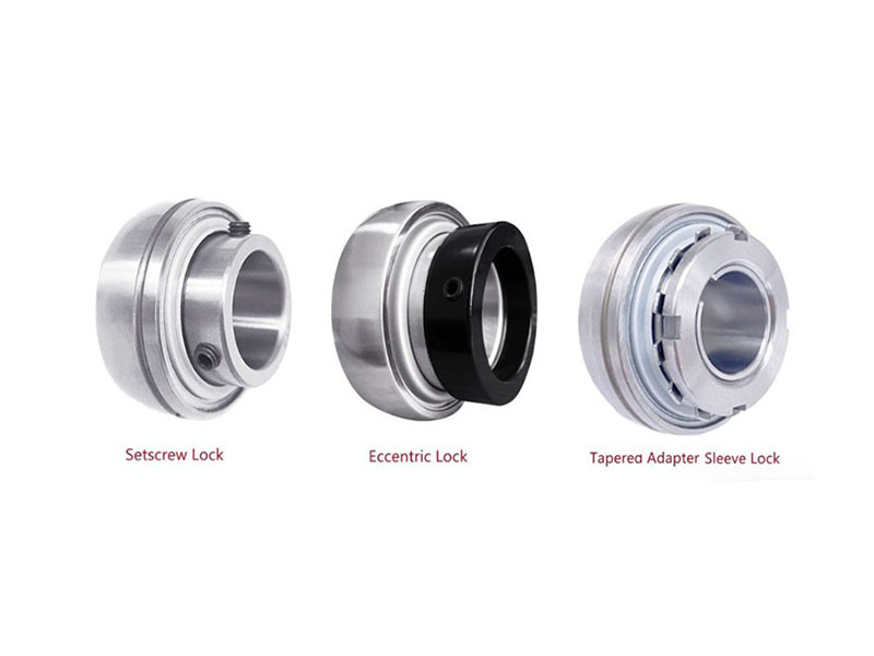
Insert bearings are locked onto shafts using three primary methods: set screw locking (UC/SA/SB series), eccentric collar locking (UE/UEL series), and adapter sleeve locking (UK series). Set screw locking is the most common and cost-effective for low-to-medium speed bidirectional applications. Eccentric collar locking provides positive binding for unidirectional drives. Adapter sleeve locking offers the highest concentricity and holding power for high-speed, high-precision applications. The right choice depends on your application’s speed, vibration, and rotation direction.
Insert bearings – deep groove ball bearings with a spherical outer surface and an extended inner ring – are widely used in agricultural machinery, conveyor systems, food processing equipment, and automotive applications. They mount into housings (pillow blocks, flange units, take-up units) and lock onto shafts using one of several mechanisms. These locking collars are also commonly referred to as mounted bearing locking collars, though the bearing insert itself is the component being locked.
Choosing the right locking method isn’t just about price or availability. The wrong choice can lead to shaft damage, premature bearing failure, unplanned downtime, and costly repairs. If you’ve ever wondered why a bearing keeps working loose on a vibrating conveyor, or why a high-speed fan bearing runs hot, the locking method is often the culprit.
Set Screw Locking (UC / SA / SB Series)
What It Is
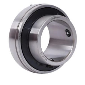
Set screw locking – also called grub screw locking – is the most common insert bearing locking method on the market. The bearing’s extended inner ring contains two set screws (cup-point hexagonal socket screws) positioned approximately 120 degrees apart. When tightened, these screws press directly against the shaft surface, creating friction that locks the bearing in place.
UC series bearings have the inner ring extended on one side. SA and SB series are variants with different dimensional or sealing configurations.
Installation Procedure
Proper installation is critical for set screw locking to work reliably:
- Shaft preparation – The shaft must be clean, free from burrs, straight, and of proper diameter. Worn shaft sections should be avoided. Shaft hardness greater than HRC 45 will reduce the effectiveness of locking devices.
- Position the bearing – Slide the bearing unit onto the shaft and move it to the predetermined position. Avoid twisting during installation, and do not tap the inner ring side or rubber seal directly.
- Tighten the set screws – Tighten each set screw incrementally, alternating between the two screws, to the recommended torque values specified in the manufacturer’s technical documentation. Do not fully tighten one screw before starting the other – this ensures even clamping force.
- Additional security – For applications with significant vibration or shock loads, consider spot drilling or filing a flat spot on the shaft where the set screws make contact. This gives the screw points a positive seat and prevents the bearing from working loose.
Performance Characteristics
Strengths:
- Most widely available and cost-effective option
- Simple installation requiring only a hex key (Allen wrench)
- Suitable for bidirectional shaft rotation
- Quick to mount and dismount
Limitations:
- Smallest contact area with the shaft among all locking methods – only the set screw points contact the shaft surface
- Prone to loosening under heavy vibration or shock loads
- Not suitable for high-speed applications because shaft tolerance significantly influences permissible speed
- Set screws can leave indentations on the shaft surface
Recommended Applications
Set screw locking is best suited for:
- Low to medium-speed bidirectional drives
- Applications with minimal shock or vibration
- Cost-sensitive projects where simplicity is prioritized
- General industrial equipment, conveyors, fans, and agricultural machinery
Eccentric Collar Locking (UE / UEL Series)
What It Is
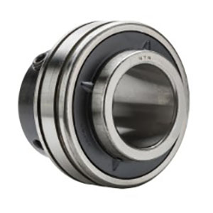
Eccentric collar locking uses an offset collar that mates with a matching eccentric surface on the bearing’s inner ring. When the collar is rotated in the direction of shaft rotation, the eccentric surfaces engage and create a positive binding action that grips the shaft tightly. A set screw on the collar provides supplementary locking.
UE series bearings have the inner ring extended on one side. UEL series bearings have the inner ring extended on both sides, providing smoother running and reduced inner ring tilt.
Installation Procedure
Eccentric collar installation requires attention to rotation direction:
- Pre-installation check – Before sliding the eccentric locking collar onto the shaft, verify that the tips of the set screws do not protrude from the inside diameter of the bearing. If a tip protrudes, loosen the set screw.
- Position the bearing – Slide the insert bearing unit onto the shaft slowly and bring it to the predetermined position. Mount the unit on the machine base and secure it firmly with bolts.
- Engage the eccentric collar – Press-fit the eccentric part of the locking collar into the eccentric part on the bearing inner ring.
- Tighten in the rotation direction – Tighten the eccentric locking collar in the shaft rotation direction. The collar must be rotated in the direction the shaft will turn during operation. For bidirectional systems, tighten the collar by hand first, then use a larger torque with tools such as a chisel or punch into the collar drill hole, tapped with a plastic hammer.
- Secure the set screw – Tighten the set screw with a hex wrench to secure the collar to the shaft. The tightening force can be the same level as that used for common set screw types.
- Pair installation – When using two eccentric collar bearings in pairs, mount both eccentric locking collars on the outside or both on the inside – do not mix orientations.
Performance Characteristics
Strengths:
- Better shaft engagement than set screw locking
- Self-tightening action that increases with use
- No shaft surface damage from set screw indentations
- More dependable across various applications than basic set screws
- Eliminates the need for locknuts, lockwashers, shoulders, sleeves, and adapters
Critical Limitation:
- Only suitable for unidirectional drives – If the shaft reverses direction, the eccentric collar can loosen. For bidirectional applications, choose set screw or adapter sleeve locking.
Additional Limitations:
- Not recommended for high-speed applications
- The eccentric action forces the shaft to one side of the inner race, affecting balance at high speeds
Recommended Applications
Eccentric collar locking is best suited for:
- Unidirectional drives where rotation is constant
- Agricultural and industrial applications where ease of installation is valued
- Applications where shaft surface damage from set screws is unacceptable
- Specific power transmission challenges where positive binding is beneficial
Adapter Sleeve Locking (UK Series)
What It Is
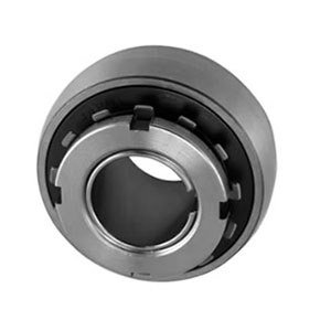
Adapter sleeve locking – also called tapered adapter mounting – uses an assembly consisting of an adapter sleeve (tapered), a locknut, and a lockwasher. The bearing has a tapered bore (1:12 taper) that matches the adapter sleeve. When the locknut is tightened, the sleeve is drawn into the bearing’s tapered bore, expanding the sleeve and clamping it firmly onto the shaft.
UK series bearings are designed specifically for adapter sleeve mounting and are available in 200 and 300 series configurations for different load capacities.
Installation Procedure
Adapter sleeve installation is the most precise and demanding of the three methods:
- Inspect components – Check that the base is rigid, the mounting surface is flat, and the shaft meets the required tolerance. Inspect the shaft for bends, burrs, or other defects.
- Mount the adapter sleeve – Slide the adapter sleeve onto the shaft to the desired position. If the sleeve feels too tight, insert a screwdriver into the sleeve slot and gently expand it.
- Position the bearing – Slide the bearing unit over the shaft and onto the adapter sleeve. Place a cylindrical reinforcing ring against the inner ring on the front side of the bearing. Seat the sleeve by lightly tapping around the back side.
- Install lockwasher and locknut – Fit the lockwasher so its tab engages with the sleeve slot. Thread the locknut onto the sleeve with the tapered side facing the bearing, and tighten by hand until hand-tight. Leave approximately 6.35 mm (1/4 in.) between the lockwasher and the inner ring of the bearing before final tightening.
- Tighten the locknut – Use a calibrated torque wrench with a hook spanner to tighten the locknut to the recommended torque values (per ISO 2982 / SKF mounting standards). A general guideline: tighten enough by hand, then rotate 2/5 to 3/5 of a revolution with a spanner. Torque values vary by bearing size:
| Bearing Series | Bore Code | Recommended Torque |
|---|---|---|
| UK 200 series | 7 | 40-60 Nm |
| UK 200 series | 12 | 130-195 Nm |
| UK 300 series | 7 | 60-90 Nm |
| UK 300 series | 12 | 225-338 Nm |
- Secure the locknut – Bend one tab of the lockwasher into a slot on the locknut to prevent loosening.
- Final check – Rotate the shaft by hand to ensure it rotates freely. Tighten the housing mounting bolts to the recommended torque.
The Tightening Dilemma
Adapter sleeve installation requires precise torque control with very little margin for error:
- Under-tightening – The sleeve may loosen, causing the bearing to spin on the shaft, leading to slippage, wear, and premature failure.
- Over-tightening – The inner ring expands, reducing internal ball clearance, which generates excessive heat and can cause bearing failure.
Always follow the manufacturer’s specified torque values or tightening angles.
Performance Characteristics
Strengths:
- Best shaft concentricity among all locking methods
- Highest holding power – largest contact area with the shaft
- Prevents fretting corrosion under adverse conditions
- Accommodates undersized shafting – tapered design provides ample tolerance margin
- Suitable for high-speed operation and reversing/indexing applications
- No shaft surface damage – no set screw indentations
- Excellent for applications exposed to excessive vibration and impact
Limitations:
- Most complex and time-consuming installation – requires multiple tools (hook spanner, torque wrench)
- Minimal installation tolerance – precise torque control is essential
- Larger assembly requires larger bearings, housings, and center shaft height
- Higher cost than other locking methods
Recommended Applications
Adapter sleeve locking is best suited for:
- High-speed applications where shaft centering is critical
- High-precision positioning requirements
- Heavy loads and severe vibration conditions
- Applications where shaft diameter tolerances are less controlled
- Reversing and indexing applications
Comparison Summary
| Locking Method | Series | Locking Principle | Key Strength | Key Limitation | Best For |
|---|---|---|---|---|---|
| Set Screw | UC / SA / SB | Set screws press directly against shaft | Lowest cost, simplest installation | Small contact area, prone to loosening, shaft damage | Low-to-medium speed, bidirectional, low vibration |
| Eccentric Collar | UE / UEL | Eccentric surfaces bind under rotation | Self-tightening action, no shaft damage | Unidirectional only, not for high speed | Constant-direction drives, agriculture, industrial |
| Adapter Sleeve | UK | Tapered sleeve expanded by locknut | Highest concentricity, strongest hold, high speed capable | Complex installation, precise torque required | High speed, heavy loads, high precision |
Conclusion
Selecting the right insert bearing locking method comes down to understanding your application’s specific demands. There’s no single “best” option – each method has clear strengths and limitations that make it suitable for different scenarios.
Choose set screw locking (UC/SA/SB) if you need a cost-effective, straightforward solution for low-to-medium speed bidirectional applications with minimal vibration. It’s the industry workhorse for a reason.
Choose eccentric collar locking (UE/UEL) if your drive operates in one direction only and you want to avoid shaft damage from set screws. Just remember: never use it in bidirectional applications.
Choose adapter sleeve locking (UK) for high-speed, high-precision, or heavy-load applications where concentricity and holding power are critical. Be prepared for more careful installation and larger overall assembly dimensions.
When evaluating these three common insert bearing locking methods, remember that your specific operating conditions – speed, vibration, load direction, and shaft tolerance – will ultimately determine the best fit.
At DUHUI Bearing, we manufacture a full range of insert bearings with all three locking methods, serving automotive OEM and aftermarket customers worldwide since 2003. Our IATF 16949-certified production facility ensures consistent quality across every bearing we ship. Whether you need UC series for a conveyor system, UE series for agricultural equipment, or UK series for high-speed machinery, we can help you select the right locking method for your application.
For technical specifications, installation torque charts, or application engineering support, contact our team at sales@duhuibearing.com – we’re here to help you get the right bearing for the job.
FAQs
Q: What’s the difference between set screw locking and adapter sleeve locking?
A: Set screw locking uses two screws that press directly against the shaft surface – contact is limited to the screw points, creating point-contact friction. Adapter sleeve locking uses a tapered sleeve that expands when the locknut is tightened, creating 360-degree contact between the sleeve and shaft. Adapter sleeve locking provides significantly higher holding power, better concentricity, and no shaft surface damage, but requires more complex installation.
Q: Why can’t eccentric collar locking be used for bidirectional drives?
A: Eccentric collar locking relies on the shaft’s rotation to maintain the binding action – the collar tightens as it turns in the direction of rotation. If the shaft reverses direction, the collar can loosen. For bidirectional applications, use set screw or adapter sleeve locking.
Q: What should I do if set screw locking keeps loosening under vibration?
A: Two solutions: First, file a flat spot or drill a small dimple on the shaft where the set screws make contact – this gives the screw points a positive seat. Second, consider upgrading to eccentric collar or adapter sleeve locking, which are more resistant to vibration-induced loosening.
Q: How do I know if I’ve tightened an adapter sleeve locknut correctly?
A: Always use a calibrated torque wrench and follow the manufacturer’s specified torque values or tightening angles. A general rule of thumb: tighten by hand, then rotate 2/5 to 3/5 of a revolution with a spanner. Under-tightening causes slippage; over-tightening reduces internal clearance and can cause overheating and failure.
Q: What shaft tolerance should I use for insert bearings?
A: Insert bearings typically accommodate drawn shafts with tolerance grades h6 to h9. For higher loads and higher speeds, manufacture the shaft to h6 or h7 tolerance. Shaft tolerance significantly influences the permissible speed for set screw and eccentric collar bearings – if using tolerances other than h6, consult the manufacturer’s technical specifications.
Q: How do I choose between UC, UE, and UK series bearings?
A: Base your decision on three factors: rotation direction (bidirectional to UC set screw; unidirectional to UE eccentric collar), speed (low-to-medium to UC or UE; high to UK adapter sleeve), and installation preference (simple to UC; precise to UK). UC is the most common and cost-effective; UK offers the best performance but requires the most careful installation.