While many gears are designed to connect parallel or intersecting shafts, the worm gear excels at transmitting motion and power between non-parallel, non-intersecting shafts, typically at a 90-degree angle. More than just a right-angle drive, it is the go-to mechanism for achieving dramatic speed reductions in a single, compact stage. From the elevators that lift us skyward to the conveyor belts that drive modern industry, worm gears are the unsung heroes of controlled, high-torque movement.
This comprehensive guide will delve deep into the world of worm gears. We will explore their working principle, dissect their various types, weigh their advantages against their limitations, and provide a practical framework for selecting the perfect worm gear set for your specific engineering challenge.
How Do Worm Gears Work?
At its core, a worm gear system is a story of two components working in harmony through a fascinating physical interaction. The worm, which resembles a screw, rotates and its threads push against the teeth of the worm wheel (or gear). This action forces the wheel to rotate.
The magic lies in the sliding action. Unlike the rolling contact seen in spur or helical gears, the teeth of a worm and wheel slide against each other. This sliding motion is what enables the high reduction ratios. For every full rotation of the worm, the wheel advances by only one tooth (if it’s a single-start worm). This inherent mechanical advantage is the foundation of its power.
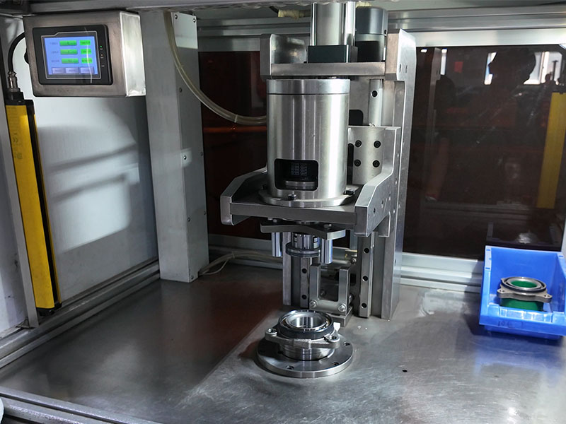
The efficiency and longevity of this interaction depend heavily on precision manufacturing. A perfectly cut worm thread ensures a smooth, consistent contact pattern on the wheel teeth, minimizing friction and wear. This is where decades of manufacturing expertise, like DUHUI’s 20 years in the industry, become critical in producing reliable, high-performance gear sets.
The Core Components of a Worm Gear System
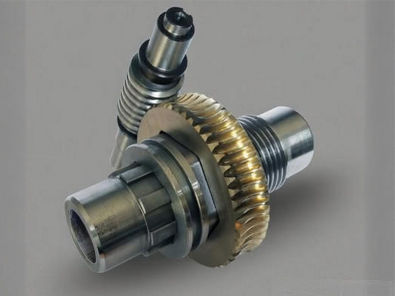
A worm gear system is elegantly simple, consisting of two primary parts:
- The Worm: This is the input component, looking very much like a threaded screw. It can have one “start” (single-thread) or multiple “starts” (multi-thread). The number of starts directly influences the gear ratio and the speed of the system.
- The Worm Wheel (or Worm Gear): This is the output component. Its teeth are specially curved to wrap around the worm, maximizing the surface area in contact. This unique tooth profile is what allows it to efficiently engage with the worm’s threads.
The Main Types of Worm Gears
Not all worm gears are created equal. They are primarily classified by the shape of their components and how they envelop each other, which directly impacts their performance characteristics.
Non-Throated Worm Gears (Cylindrical)
- Characteristics: This is the simplest form, where both the worm and the wheel maintain a straight, cylindrical profile. The contact between them is essentially a point.
- Trade-offs: Due to the minimal point contact, their load-carrying capacity is the lowest. They are suitable only for very light loads, infrequent use, or as adjusting mechanisms where low friction is more important than power.
Single-Throated Worm Gears (Single-Enveloping)
- Characteristics: This is the most common and versatile type. The worm wheel is concave, or “throated,” to wrap around the cylindrical worm. This design increases the contact from a point to a line.
- Trade-offs: The line contact significantly boosts load capacity and power handling compared to the non-throated type. It offers a strong balance of performance, durability, and manufacturability, making it the standard choice for a vast range of industrial applications.
Double-Throated Worm Gears (Double-Enveloping)
- Characteristics: This is the pinnacle of worm gear design. Here, both the worm and the wheel are throated, meaning they both have a concave shape and wrap around each other. This creates an area contact, with both components conforming to each other’s curvature.
- Trade-offs: This configuration provides the highest possible load capacity and shock resistance of any worm gear type. However, this comes at a cost. They are the most complex and expensive to manufacture, have the lowest efficiency due to maximum sliding contact, and require a perfectly maintained oil film to prevent failure.
How to Calculate Gear Ratio
The gear ratio is the heart of a gearbox’s function, defining the relationship between input speed and output torque. For worm gears, the calculation is straightforward:
Gear Ratio (i) = Number of Teeth on Worm Wheel (Z₂) / Number of Starts on Worm (Z₁)
Example: Imagine you have a double-start worm (Z₁=2) driving a worm wheel with 60 teeth (Z₂=60). The gear ratio is 60 / 2 = 30:1. This means it takes 30 revolutions of the worm to turn the wheel just once, multiplying the input torque by approximately 30 times.
A single-start worm (Z₁=1) can achieve very high ratios, such as 60:1 or even 100:1, in a single reduction stage, a feat that would require multiple stages with other gear types.
The Key Advantages of Worm Gears
Worm gears are chosen for specific applications because of a unique set of benefits:
- High Reduction Ratios: As mentioned, they provide immense speed reduction and torque multiplication in a single, compact stage, saving space and simplifying mechanical design.
- Self-Locking Capability: In many configurations, especially those with a single-start worm and a low lead angle, the system becomes self-locking. This means the worm wheel cannot drive the worm. This is a critical safety feature in applications like hoists, elevators, and conveyor systems, preventing the load from back-driving the motor when power is cut.
- Quiet and Smooth Operation: The sliding action, while less efficient, is inherently smoother and quieter than the impacting contact of spur gears. This makes them ideal for environments where noise reduction is a priority.
- Compact Design: The right-angle output allows for flexible and space-saving machine layouts, fitting into tight corners where other drive systems cannot.
- High Shock Load Resistance: The mass of the worm wheel, often made of bronze, and the sliding contact can absorb and dampen shock loads, protecting the more expensive connected machinery.
The Limitations of Worm Gears
Despite their strengths, worm gears have inherent limitations that engineers must consider during the design phase:
- Lower Efficiency: The constant sliding friction generates heat and power loss. Efficiencies can range from as low as 50% for high-ratio, self-locking gears to about 90% for optimized, multi-thread designs. This is a critical factor in energy-sensitive applications.
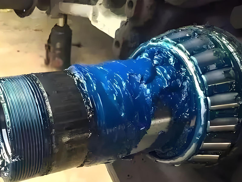
- High Lubrication Demand: The sliding motion requires a continuous and robust oil film to prevent metal-to-metal contact. Special high-viscosity oils with extreme pressure (EP) additives are essential for longevity.
- Limited High-Speed Applicability: At high input speeds, the heat generated by friction can become excessive, leading to lubricant breakdown and gear failure. They are generally not suitable for continuous, high-horsepower, high-speed applications without complex cooling systems.
The Material Selection of Worm Gears
At DUHUI Bearing, we know that the choice of materials is not just a specification; it’s the defining factor in a gear set’s lifespan and performance. The pairing is typically strategic:
The Worm – Built for Strength: The worm must be exceptionally hard and smooth. It is typically made from hardened steel (like 20CrMnTi or 40Cr), carburized, and precision-ground to create a durable, low-friction surface. For corrosive environments, stainless steel worms are used.
The Worm Wheel – The Sacrificial Element: To protect the more expensive and difficult-to-manufacture worm, the wheel is made from a softer material. This allows it to “wear in” and conform to the worm’s shape.
- Bronze (e.g., Phosphor Bronze): The premium choice. It has excellent anti-weld properties, high strength, and can embed small contaminants, protecting the steel worm. It’s the standard for heavy-duty, continuous operation.
- Brass / Cast Iron: Used for lighter loads, lower speeds, or intermittent duty where cost is a primary concern.
- Nylon / Plastics: Ideal for very light loads, food-grade applications where lubrication must be avoided, or in environments where corrosion is a major issue.
The Lubrication of Worm Gear
Lubrication is non-negotiable for a worm gear’s success. It performs three vital functions:
- Prevents Metal-to-Metal Contact: It creates a thin but strong hydrodynamic film that separates the sliding surfaces.
- Reduces Friction and Improves Efficiency: A good lubricant minimizes the energy lost to heat.
- Dissipates Heat: It carries away the heat generated by friction, helping to maintain a safe operating temperature.
For most industrial applications, synthetic oils (Polyalphaolefin – PAO, or Polyalkylene Glycol – PAG) are highly recommended. They offer a higher viscosity index and better thermal stability than mineral oils, ensuring a reliable oil film across a wider temperature range.
How to Select the Right Worm Gear for Your Application
Choosing the correct worm gear involves more than just matching a ratio. It requires a holistic view of your application’s demands. Consider these key parameters:
- Load: What is the required output torque? This dictates the size and material of the gear set.
- Speed: What are the input and output speeds? This, combined with the load, determines the power and thermal requirements.
- Duty Cycle: Will the gear run continuously for 24 hours, or just for a few seconds every minute? Continuous operation requires derating to manage heat.
- Environment: Is the gearbox exposed to dust, moisture, chemicals, or extreme temperatures? This influences the choice of materials, seals, and lubricants.
- Space: What are the physical mounting constraints? This determines the center distance and housing style.
- Efficiency Targets: How critical is energy consumption to your overall system? This will guide the choice between, say, a single-throated and a more efficient, multi-thread design.
Common Applications Across Industries
The unique characteristics of worm gears make them indispensable in countless applications:
- Material Handling & Lifting: The self-locking feature is a key safety requirement in elevators, hoists, and conveyors. Gate openers also rely on this to prevent the gate from being forced open.
- Industrial Automation: In conveyors, mixers, and packaging machinery, their compact size and high torque output at low speeds are perfectly suited for moving and processing materials.
- Precision Control & Adjustment: The ability to make fine, controlled adjustments makes them ideal for indexing tables in machine tools and even for tuning adjustments in some musical instruments.
- Compact & Right-Angle Drives: Their space-saving design is why they are used in vehicle differentials, automotive seat adjusters, and small actuators where space is at a premium.
Frequently Asked Questions (FAQ)
1. Can a worm gear be back-driven?
It depends on the lead angle of the worm. If the lead angle is small (typically less than 5-6 degrees), the friction in the system will prevent the gear from driving the worm, making it self-locking. Multi-start worms with higher lead angles can often be back-driven.
2. Worm gear vs. helical gear: which one is right for me?
If you need a high reduction ratio in a single stage, a right-angle output, or a self-locking feature, a worm gear is the better choice. If your priority is the highest possible efficiency for continuous power transmission between parallel shafts, a helical gear unit is superior.
3. Do worm gears require special cooling?
For standard, intermittent duty cycles, the gearbox housing is usually sufficient to radiate the generated heat. However, for high-power, continuous-duty applications, external cooling—such as a fan on the input shaft, a cooling coil in the oil sump, or even a circulating pump—may be necessary to prevent overheating.
4. What is the typical efficiency range of a worm gear drive, and why is it lower than other gear types?
The efficiency of a worm gear drive typically ranges from 50% to 90% . Lower ratios (e.g., 5:1 to 15:1) with optimized lead angles can achieve 85–90% efficiency, while higher ratios (above 30:1) often drop to 50–70%. The primary reason for lower efficiency is the sliding action between the worm and worm wheel, which generates significant friction, unlike rolling contact in spur or helical gears. This sliding friction increases with higher reduction ratios and is why worm gears are generally not recommended for continuous high-power transmission.
5. Does every worm gear have a self-locking feature? What conditions must be met?
No, self-locking is not automatic. A worm gear is self-locking when the lead angle of the worm is smaller than the friction angle of the mating materials. In practical terms, this typically occurs when the lead angle is below 4° to 6° , which corresponds to reduction ratios approximately above 30:1 to 40:1 (for a single-start worm). Even under these conditions, self-locking is not absolute: vibration, shock loads, or poor lubrication can break the static friction, allowing back-driving. Manufacturers should always verify self-locking with actual operating conditions, as surface finish and lubricant type also affect friction.
6. Why is bronze the most common material for worm wheels, and what alternatives exist?
Bronze, specifically phosphor bronze (e.g., CuSn12) or aluminum bronze, is preferred for worm wheels because it has excellent embedability (allows fine abrasive particles to embed without scoring the steel worm), high compressive strength, and low friction against hardened steel. The combination of a hardened steel worm and a bronze wheel provides the best wear resistance and anti-seizing properties. Alternatives include cast iron (for low-speed, light-load applications), aluminum alloys (limited use due to lower strength), and engineering plastics (e.g., nylon or POM – for very light duty, low-noise applications). However, bronze remains the industry standard for most industrial worm gears due to its thermal conductivity and fatigue resistance.
7. How do you determine the correct lubricant viscosity for a worm gear?
For most industrial worm gears, ISO VG 220 to 460 mineral or synthetic gear oils are used. The specific viscosity depends on:
- Operating speed: Higher input speeds (>1500 rpm) require lower viscosity (ISO 220) to reduce churning losses.
- Ambient temperature: High-temperature environments (above 50°C) need higher viscosity (ISO 460) to maintain film strength.
- Load condition: Heavy or shock loads require higher viscosity or EP (extreme pressure) additives.
Important: Worm gears should never use lubricants with high levels of sulfur-phosphorus EP additives unless the manufacturer explicitly approves them, as these can corrode bronze worm wheels. Polyalphaolefin (PAO) synthetic oils are often preferred for their thermal stability and longer drain intervals.
8. Can worm gears operate effectively at high rotational speeds?
Generally, no. Worm gears are not suitable for high input speeds (typically above 3000 rpm for the worm shaft) due to three limiting factors:
- Heat generation: Sliding friction increases with speed, leading to excessive oil temperatures (above 100°C) that degrade lubricant and cause tooth seizure.
- Reduced efficiency: At high speeds, churning losses become significant, and efficiency drops further.
- Limited PV value: The product of pressure (P) and velocity (V) exceeds the allowable limit for bronze-steel pairs, accelerating wear.
For applications requiring input speeds above 1800 rpm, forced lubrication (oil pump and cooler) is mandatory. In most cases, worm gears are best suited for moderate speeds (500–1500 rpm input) with high reduction ratios.
9. What is the difference between single-start, double-start, and multi-start worm gears?
The number of “starts” refers to the number of independent helical threads on the worm.
- Single-start worm: One continuous thread. For every full turn of the worm, the worm wheel advances by one tooth. Provides the highest reduction ratio (e.g., 60:1) and strongest self-locking tendency, but lowest efficiency (50–60%).
- Double-start worm: Two parallel threads. One worm turn advances the wheel by two teeth. Ratio is halved compared to a single-start of the same diameter, but efficiency increases (70–75%).
- Multi-start worms (3 or more starts): Even lower ratios (down to 5:1) and higher efficiencies (up to 90%), but self-locking is lost. Selection involves a trade-off: use single-start for holding loads (hoists, lifts) and multi-start for higher speed, lower torque transmission.
10. How does center distance affect worm gear performance and durability?
The center distance (distance from worm axis to worm wheel axis) is a fundamental design parameter that directly influences load capacity and service life. For a given ratio:
- Increasing center distance allows larger tooth contact areas, reduces Hertzian contact stress, and increases torque capacity and fatigue life. However, it also increases size, weight, and cost.
- Standardized center distances (e.g., 40 mm, 63 mm, 100 mm, 160 mm per ISO/AGMA) should be preferred to use off-the-shelf hobs and gauges.
A rule of thumb: doubling the center distance approximately increases torque capacity by a factor of 2.5 to 3, but housing rigidity must also be increased. When replacing a worm gear, always maintain the exact original center distance; a mismatch of even 0.5 mm causes edge loading and premature failure.
11. What is backlash in a worm gear, and how can it be adjusted or minimized?
Backlash is the rotational play between the worm and worm wheel when the direction of rotation is reversed. In worm gears, backlash is necessary to prevent binding due to thermal expansion and lubricant film thickness. Typical acceptable backlash ranges from 0.05 mm to 0.25 mm for general industrial applications.
To minimize backlash:
- Use adjustable split worm wheels (two halves that can be rotated relative to each other to take up clearance).
- Specify precision ground worms with tighter tooth profile tolerances (AGMA Class 10 or higher).
- Reduce center distance tolerance through precision machining (e.g., line boring housings).
For zero-backlash applications (e.g., robotic joints, instrument drives), consider using dual-lead (dual-pitch) worm gears where one flank maintains contact, or pre-loaded spring mechanisms. However, note that zero backlash increases friction and wear.
Conclusion & Expert Advice
Worm gears are a masterclass in mechanical ingenuity, offering a unique combination of high reduction, compactness, and safety that few other drive systems can match. Understanding their principles, types, and application-specific nuances is key to unlocking their full potential.
Selecting the right worm gear involves navigating a complex interplay of load, speed, duty cycle, and material science. You don’t have to do it alone. With 20 years of experience in manufacturing high-quality bearings and power transmission components, DUHUI Bearing possesses the engineering expertise to guide you.