Getting bearing clearance wrong by just a few thousandths of an inch can destroy an engine within minutes of first start. This is why understanding how to measure and select the correct clearance—whether for connecting rod bearings or main bearings—is the foundation of professional engine assembly.
In this guide, you will learn the measurement process, the formula for calculating clearance, how to interpret standard clearance charts, and how to choose between tighter or looser clearances for your specific application.
What Is Bearing Clearance?
Bearing clearance (also called oil clearance) is the measured gap between the inner surface of a bearing shell and the surface of the rotating shaft journal—typically a crankshaft main journal or connecting rod journal. This gap is deliberately engineered to:
- Provide space for a hydrodynamic oil film
- Accommodate thermal expansion during operation
- Allow for minor shaft deflection under load
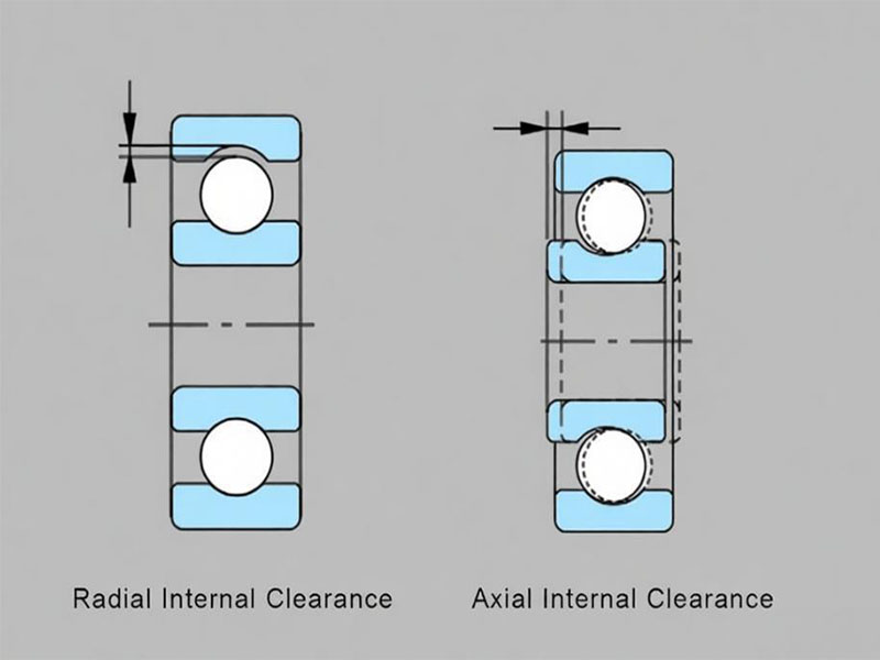
It is important to distinguish between internal clearance (the slack inside the bearing before installation) and assembled oil clearance (the working gap measured after the bearing is installed and torqued to specification). This guide focuses on assembled oil clearance, as this determines engine performance and longevity.
Why Proper Bearing Clearance Matters
During engine operation, the crankshaft does not make direct contact with the bearing surface. Instead, it rides on a thin, pressurized film of oil called the hydrodynamic oil wedge. This oil wedge prevents metal-to-metal contact, absorbs shock loads, and dissipates heat.
Insufficient Clearance (Too Tight)
When clearance is too tight, the oil film cannot form properly. This leads to boundary lubrication, rapid overheating, bearing scuffing, and eventual seizure.
Excessive Clearance (Too Loose)
When clearance is too loose, the oil wedge becomes unstable. Pressurized oil escapes too quickly, causing a drop in oil pressure. The most recognizable symptom of excessive clearance is a low-frequency knocking sound that changes with engine RPM—commonly referred to as rod knock. Over time, this leads to fatigue failure and bearing flaking.
How to Measure Bearing Clearance (Step-by-Step)
Professional measurement requires proper tools and technique.
Tools Required
- Outside micrometer (0.0001″ / 0.001mm resolution)
- Dial bore gauge
- Torque wrench (calibrated to spec)
- Clean shop towels and solvent
Step 1 – Clean and Prepare
Thoroughly clean all bearing shells, crankshaft journals, and the bearing housing bore. Any debris will distort the measurement.
Step 2 – Measure the Crankshaft Journal
Using a micrometer, measure each journal in at least three positions around its circumference to detect out-of-round conditions. Record the smallest reading. Also check whether the crankshaft has been previously machined (e.g., 0.010″, 0.020″, or 0.030″ undersize), as replacement bearings must match those reduced journal diameters.
Step 3 – Install Bearing Shells and Torque
Install the bearing shells into their housings (engine block for mains, connecting rods for rod bearings). Apply a thin film of engine oil to bolt threads and under bolt heads, then torque to the engine manufacturer’s specification.
Step 4 – Measure Assembled Bearing ID
Use a dial bore gauge to measure the assembled bearing’s inside diameter. Take measurements at 90 degrees to the parting line—this provides the minimum clearance reading. Avoid measuring directly at the parting line, as bearings have a parting line relief designed to allow for minor mismatches between the upper and lower shells.
Step 5 – Calculate Clearance
Formula: Bearing Clearance = Assembled Bearing ID – Crankshaft Journal Diameter
Example:
– Measured crankshaft journal diameter: 2.1650″
– Measured assembled bearing ID after torquing: 2.1672″
– Calculated clearance: 0.0022″
If you zeroed your dial bore gauge to the exact measured journal diameter before measuring the bearing, the gauge will read clearance directly.
Plastigage vs Dial Bore Gauge
Plastigage provides a quick approximate check. For accurate, repeatable measurements—especially in professional engine building or when tight tolerances are required—a dial bore gauge and micrometer are superior.
Pro Tip: Always double-check your measurements. Tolerance stack-up can reduce or increase effective clearance by up to 0.0005″ even when each component is within its individual specification.
How to Calculate Bearing Clearance: Formula & Example
The widely accepted rule-of-thumb among engine builders is 0.001″ of clearance per 1 inch of shaft diameter. For a main bearing journal measuring 2.100″, this calls for approximately 0.0021″ of clearance.
Standard clearance ranges:
| Bearing Type | Typical Clearance (inch) | Typical Clearance (mm) |
|---|---|---|
| Main bearing (street) | 0.0015″ – 0.0025″ | 0.038 – 0.064 mm |
| Rod bearing (street) | 0.0010″ – 0.0020″ | 0.025 – 0.051 mm |
| High-performance / racing | Add 0.0005″ – 0.0010″ | Add ~0.013 – 0.025 mm |
For performance use, target the upper half of the standard range or add 0.0005″–0.0010″ depending on oil viscosity and RPM.
Note for extra clearance: Bearings marked “X” (extra clearance) add approximately 0.001″ when both halves are used. Mixing one X-shell with one standard shell adds 0.0005″. This is useful when tolerance stack-up has reduced clearance below spec.
Tight vs Loose Bearing Clearance – Which One Should You Select?
Choosing the correct clearance depends on the engine’s intended application.
Tighter Clearances (Street / Daily Driver)
- Maintain higher oil pressure at low RPM
- Reduce oil leakage past bearings
- Provide quieter operation
- Suitable for moderate temperature ranges
Looser Clearances (Racing / High-Performance / Heavy Load)
- Allow increased oil flow for better cooling
- Accommodate higher operating temperatures
- Reduce friction slightly at high RPM
- Require thicker oil (higher viscosity) to maintain pressure
Real-World Example: Tolerance Stack-Up
A main bearing bore that is 0.0003″ on the tight side of its tolerance, combined with a crankshaft journal that is 0.0002″ too large—both within spec individually—can stack up to reduce clearance by nearly 0.0005″. The final clearance may fall below the recommended minimum. In such cases, using one extra-clearance shell can restore proper clearance.
Common FAQs About Bearing Clearance
Q1: What happens if bearing clearance is too tight?
A1: Metal-to-metal contact, overheating, scoring, and potential seizure.
Q2: What happens if bearing clearance is too loose?
A2: Low oil pressure, rod knock (a low-frequency knocking sound), and eventual bearing fatigue failure.
Q3: What is the best way to check bearing clearance?
A3: Dial bore gauge and micrometer provide accurate, repeatable measurements. Plastigage is acceptable for quick verification.
Q4: Can I mix and match bearing shells to adjust clearance?
A4: Yes. Mixing a standard shell with an extra-clearance shell adds approximately 0.0005″. The standard (thicker) half should be placed in the higher-load position—cap side for mains, upper side for connecting rods.
Q5: How does oil viscosity affect bearing clearance?
A5: Thicker oil helps fill a looser gap and maintain pressure. Thinner oil flows more easily through a tight clearance. Always select viscosity after determining your assembled clearance.
Q6: Do different bearing materials affect clearance requirements?
A6: Yes. Trimetal copper-lead bearings typically require 0.0002″–0.0003″ tighter clearance than aluminum bearings for the same application. Always consult the bearing manufacturer’s specifications.
Q7: How much clearance do I need for high-RPM applications?
A7: Add 0.0005″–0.0010″ to the standard recommendation, depending on oil viscosity and expected operating temperature.
Q8: Can bearing clearance be too loose for a street engine?
A8: Yes. Excessive clearance causes low idle oil pressure, noisy operation, and accelerated wear. Street engines should be built toward the tighter side of the recommended range.
Conclusion
Whether you are setting main bearing clearance or rod bearing clearance, the same fundamental principles apply: measure, calculate, and verify. A clearance that is too tight or too loose will compromise both performance and engine life. By following the measurement procedures and clearance charts in this guide, you can select the correct fit for your specific application—whether a daily-driven street engine, a high-performance race motor, or a heavy-duty industrial machine.
About DUHUI Bearing
DUHUI Bearing is a China-based manufacturer specializing in automotive wheel hub bearings and precision engine bearings. Our products are manufactured to meet ISO standards with consistent clearances verified by ISO-compliant measurement protocols. DUHUI serves both the automotive aftermarket and industrial sectors worldwide.
View DUHUI’s bearing clearance specifications for our standard and extra-clearance product lines. Contact our team to request a catalog or discuss your specific bearing requirements.