What happens when a bearing is overloaded with axial force? Premature spalling, overheating, and unexpected downtime. Axial load — also called thrust load — is a force acting parallel to the shaft axis. Selecting a bearing without correctly evaluating its axial load capacity is a common cause of failure. This guide explains what bearing axial load is, what influences its capacity, how to calculate it, and how to select the right bearing type.
At DUHUI Bearing, a manufacturer with over 20 years of experience, engineering teams have analyzed hundreds of axial-load-related failures. The following information is based on industry standards and practical application data.
What Is Bearing Axial Load? Definition and Basics
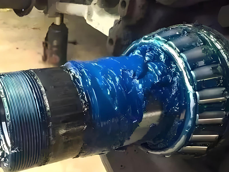
Bearing axial load refers to a force applied parallel to the shaft axis (the rotational centerline). In contrast, radial load acts perpendicular to the shaft. Many applications, such as helical gears or machine tool spindles, experience a combination of both. Axial loads can be unidirectional (acting in one direction) or bidirectional (reversing direction, like in a car wheel when turning).
Factors That Influence Bearing Axial Load Capacity
The amount of axial load a bearing can handle depends on external application factors and internal bearing design.
External Factors (Application-Related)
- Applied forces: Helical gears generate inherent axial forces; fans or turbines experience thrust from fluid flow.
- Operating conditions: High speeds and rapid acceleration create dynamic forces that alter effective axial load.
- Vibration and shock loads: Sudden peak forces can significantly exceed steady-state loads, leading to premature failure if not accounted for.
- Misalignment: Shaft deflection or housing inaccuracies can induce unwanted axial forces.
Internal Factors (Bearing Design and Properties)
- Contact angle: The most critical factor. Larger contact angles (e.g., 40° in angular contact ball bearings) enable higher axial load capacity.
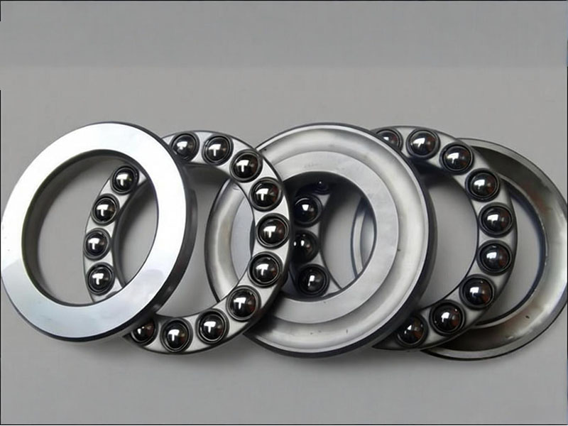
- Rolling element type: Ball bearings manage light to moderate axial loads; roller bearings (especially tapered roller bearings) excel in heavy thrust applications.
- Material properties: Steel quality, purity, and heat treatment determine hardness and fatigue resistance, directly impacting axial load endurance.
- Lubrication: A proper lubricant film distributes load evenly across contact surfaces, reducing wear.
- Load ratings: Every bearing has defined Basic Dynamic Axial Load Rating (Ca) and Static Axial Load Rating (C0a), calculated values representing the load a bearing can endure for a specific lifespan.
How to Calculate Bearing Axial Load (Step-by-Step)
Accurate calculation is essential for proper selection. Follow these steps:
- Identify all acting forces: Create a free-body diagram of the shaft assembly. Identify thrust sources such as gear forces, propeller thrust, or inertial forces during acceleration.
- Analyze load distribution: For paired bearings (common with angular contact or tapered roller bearings), axial load is distributed based on internal geometry and mounting arrangement, not simply shared equally.
- Apply the equilibrium principle: Use ∑F = 0. The sum of axial forces in one direction must equal the sum in the opposite direction. This helps solve for unknown axial force on a specific bearing.
- Calculate equivalent dynamic load (P): For combined radial and axial loads, use the formula P = X·Fr + Y·Fa, where Fr is radial load, Fa is axial load, and X and Y are load factors from the bearing catalog.
Worked example: A 6206 deep groove ball bearing under radial load 2000 N and axial load 300 N. Manufacturer catalog gives X = 0.56, Y = 1.8. Then P = 0.56 × 2000 + 1.8 × 300 = 1120 + 540 = 1660 N. This P is used in the life equation L10 = (C/P)3 for ball bearings.
Add a safety factor for real-world variations:
- Steady, low-shock loads: fn = 1.0 – 1.2
- Light to moderate shock: fn = 1.2 – 1.5
- Heavy shock or vibration: fn = 1.5 – 3.0
Bearing Axial Load Capacity by Bearing Type
The table below summarizes typical axial load capability of common bearing types.
| Bearing Type | Axial Capacity Rating |
|---|---|
| Deep Groove Ball Bearing | Low (light axial loads, low to moderate speeds) |
| Angular Contact Ball Bearing (single row) | Moderate to High (unidirectional) |
| Angular Contact Ball Bearing (back-to-back pair) | High (bidirectional) |
| Tapered Roller Bearing (single row) | High (unidirectional combined load) |
| Cylindrical Roller Bearing (without flanges) | Very low (primarily radial) |
Best Practices for Managing Axial Load
Correct Bearing Selection
- Light to moderate axial loads: Deep groove ball bearings
- High-speed, moderate thrust: Angular contact ball bearings
- Heavy axial loads and shock loads: Tapered roller bearings or cylindrical roller bearings with thrust flanges
- Always match load ratings: Select bearings with dynamic/static axial load ratings (Ca, C0a) that comfortably exceed calculated maximum loads, including safety factors.
Precision Installation and Preloading
- Proper mounting prevents misalignment and additional stress.
- Preloading creates a permanent axial load within the bearing system to remove internal clearance, increasing rigidity for applications like machine tool spindles.
Proactive Monitoring and Lubrication
- Regular monitoring: Use vibration analysis and temperature monitoring. Sudden temperature rise or changed vibration signature may signal an axial load problem.
- Maintain lubrication: Adhere to recommended relubrication intervals and use correct grease/oil type and quantity.
Consequences of Improper Axial Load Management
- Overloading: High contact stresses cause fatigue spalling (metal flaking), overheating, and premature bearing failure — a primary cause of unscheduled downtime.
- Insufficient load or control: At high speeds, too light an axial load causes rolling elements to skid instead of roll, leading to smearing and damage. In precision machinery, uncontrolled axial movement compromises accuracy and system stability.
Frequently Asked Questions (FAQ)
Q1: What is the difference between axial load and thrust load?
A1: There is no difference. Thrust load is a synonym for axial load. Both refer to a force acting parallel to the shaft axis.
Q2: Can a deep groove ball bearing handle pure axial load?
A2: Yes, but only light loads (typically ≤ 25% of its static radial rating C0) and low speeds. For pure axial load applications, thrust bearings or angular contact bearings are more suitable.
Q3: How does contact angle affect axial load capacity?
A3: Larger contact angle (e.g., 40° vs 15°) increases axial load capacity but reduces radial load capacity. Angular contact bearings use high contact angles for thrust-dominant applications.
Q4: What is the formula for bearing axial load calculation?
A4: The standard formula for combined loads is equivalent dynamic load: P = X·Fr + Y·Fa, where X and Y are from the bearing catalog. For pure axial load on a thrust-capable bearing, P = Fa.
Q5: How can I tell if axial load caused my bearing failure?
A5: Typical signs include asymmetric raceway wear (one side more damaged), spalling limited to one side of the raceway, and in severe cases, cage or rolling element fracture. Vibration analysis may show increased axial movement.
Conclusion
Proper evaluation of bearing axial load requires understanding load magnitude, direction, speed, and bearing internal geometry (contact angle, rolling element type, and pairing configuration). The calculation steps, reference tables, and best practices provided here follow industry standards and DUHUI’s two decades of manufacturing experience. For application-specific support — including load analysis and bearing recommendation — contact DUHUI’s technical team directly.