Bearing clearance—the internal gap between the rolling elements and the raceways—is a critical parameter that directly affects bearing performance, operating temperature, and service life. Too little clearance can lead to overheating and premature seizure, while excessive clearance often results in vibration, noise, and early fatigue failure. Whether you are involved in maintenance, assembly, or quality control, understanding how to measure bearing clearance accurately is essential. DUHUI covers the key methods, industry guidelines, and practical steps to help you achieve reliable results.
1. Why Bearing Clearance Measurement Matters
Proper bearing clearance ensures that the bearing operates under optimal lubrication conditions and accommodates thermal expansion during operation.
- Clearance restricts the lubricant film, increases friction, and generates excessive heat. In severe cases, it can cause the bearing to seize.
- Excessive clearance allows the shaft to move radially or axially beyond design limits, leading to vibration, noise, and uneven load distribution, which accelerates fatigue.
For rotating machinery—from automotive wheel hubs to industrial equipment—correct clearance is fundamental to reliability.
2. Preparation Before Measurement
Accurate measurement begins with proper preparation.
- Clean the components
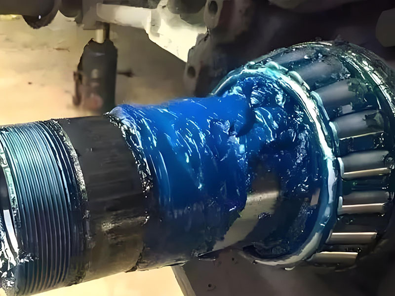
Remove any debris, old lubricant, or burrs from the bearing, shaft, and housing. Contamination is a common source of measurement error. - Ensure correct bearing installation
The bearing must be seated properly. For split housings, tighten the bolts to the specified torque before measuring. In most cases, measurements should be taken with the bearing at room temperature unless the application specifies otherwise.
3. Methods for Measuring Bearing Clearance
Different methods apply depending on the bearing type, size, and accessibility.
3.1 Dial Bore Gauge & Micrometer Method
This method is commonly used for measuring radial clearance in mounted bearings.
- Measure the housing bore diameter using a dial bore gauge.
- Measure the shaft outer diameter with a micrometer.
- Calculate clearance as the difference between the housing bore and the shaft diameter.
This approach provides high accuracy and is suitable for precision applications.
3.2 Plastigage Method
Plastigage is a simple, cost-effective method for measuring clearance in plain bearings and larger rolling bearings.
- Place a Plastigage strip along the shaft or bearing surface.
- Assemble the bearing and tighten to the specified torque.
- Disassemble and measure the flattened strip width against the provided scale.
The method is particularly useful for field inspections where specialized tools are unavailable.
3.3 Feeler Gauge Method
Feeler gauges are widely used for measuring radial clearance in split bearings and certain mounted assemblies.
- Insert the feeler gauge between the rolling element and the raceway or between the shaft and bearing surface.
- Use the thickest blade that fits with slight resistance.
- Record the measurement and repeat at multiple points to account for variations.
This method is quick but relies on operator experience. It works best for bearings with accessible clearance gaps.
4. Rule of Thumb for Bearing Clearance
While manufacturers provide specific clearance classes (e.g., C2, C3, C4), general rules of thumb can help in initial assessments:
- Minimum operating clearance = minimum internal clearance + 0.001 in (0.025 mm) as a safety margin for thermal expansion.
- A common guideline is 0.00125 inches per inch of shaft diameter (approximately 0.00125 mm per mm of shaft diameter).
These values should be treated as starting points. Always refer to the original equipment manufacturer (OEM) specifications when available.
5. What Is the Acceptable Bearing Clearance?
Acceptable clearance depends on multiple factors and varies across applications.
5.1 Factors Affecting Clearance
- Bearing type – ball bearings, cylindrical roller bearings, and tapered roller bearings have different internal geometries.
- Shaft diameter – larger shafts generally require greater clearance to accommodate thermal growth.
- Operating conditions – high-speed applications typically use tighter clearance, while high-temperature or heavy-load conditions may require increased clearance.
- Housing and shaft fit – interference fits reduce internal clearance after installation.
5.2 General Guidelines by Bearing Size
| Bearing Size | Typical Radial Clearance Range (mm) |
| Small | 0.001 – 0.005 |
| Medium | 0.002 – 0.010 |
| Large | 0.010 – 0.030 |
Note: These values are indicative. Actual specifications depend on bearing design and application.
5.3 Clearance Ranges by Bearing Type
- Deep groove ball bearings
Typical clearance: 0.003 – 0.020 mm (depending on C2, CN, C3 classes) - Cylindrical roller bearings
Typically require larger internal clearance: 0.010 – 0.050 mm - Tapered roller bearings
Often set with near-zero or slight preload; radial clearance is typically 0 – 0.010 mm when measured under light load
6. How to Adjust Bearing Clearance
Adjustable bearings—such as tapered roller bearings or bearings in split housings—allow clearance to be set during installation.
- Measure the initial clearance using one of the methods described above.
- Adjust shims or move the adjusting nut to increase or decrease clearance according to the target value.
- Re-measure to confirm the adjustment. Repeat the process until the clearance falls within the specified range.
For bearings that are not field-adjustable, selecting the correct internal clearance class during procurement is critical.
Conclusion
Measuring bearing clearance accurately is a fundamental practice in bearing installation and maintenance. Whether using dial bore gauges, Plastigage, or feeler gauges, the key lies in consistent preparation and understanding the specific requirements of each bearing type and application. Following the guidelines outlined here helps prevent common failure modes such as overheating, vibration, and premature wear. For applications requiring precise clearance control, consulting the bearing manufacturer’s technical data remains the most reliable approach.