1. Introduction to Gears
1.1 Definition
Gears are mechanical components designed to transmit power and motion between machine shafts through the sequential engagement of teeth. These toothed wheels are fundamental to virtually every mechanical system, from precision instruments to heavy industrial equipment, enabling reliable torque transmission, speed adjustment, and directional control.
1.2 Working Principle
Gears operate on the principle of leverage applied continuously. When two gears mesh, the teeth of the driving gear push against the teeth of the driven gear, creating a force that rotates the driven shaft. By pairing gears of different sizes, we achieve two critical functions: speed/torque modification and motion direction change. A smaller gear driving a larger one reduces output speed but increases torque—essential for heavy machinery requiring high force at low speeds.
1.3 Classification
Understanding gear classification helps engineers select the optimal solution for specific applications:
| Classification Basis | Categories | Description |
| Shaft Arrangement | Parallel, Intersecting, Non-parallel Non-intersecting | Determines how shafts are positioned relative to each other |
| Tooth Profile | Straight, Helical, Curved | Influences engagement smoothness and load distribution |
| Motion Type | Rotary, Linear (rack and pinion) | Defines output motion |
| Performance Characteristics | Efficiency, Load Capacity, Noise Level | Dictates application suitability |
2. Parallel Shaft Gears: Efficiency and Power Design
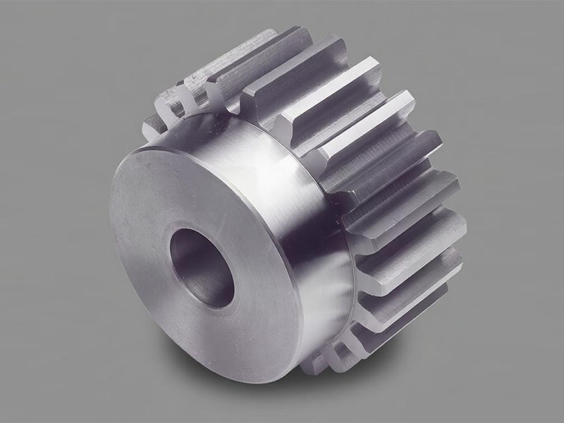
2.1 Spur Gears: Simplicity and Cost-Effectiveness
Design CharacteristicsSpur gears feature teeth cut parallel to the shaft axis, making them the simplest and most common gear type. They transmit power between parallel shafts with straightforward tooth engagement.
 Performance Attributes
- Efficiency: Up to 95% per stage due to minimal sliding friction
- Cost: Most economical to manufacture and maintain
- Limitations: Generate significant noise at high speeds due to sudden tooth engagement
- Load Capacity: Moderate, limited by single-tooth contact
Typical Applications
- Low to medium-speed industrial machinery
- Simple power transmission systems
- Agricultural equipment where noise is not critical
- Consumer appliances
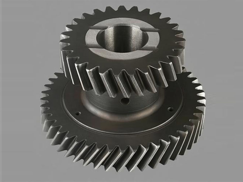
2.2 Helical Gears: Smooth Operation and High Load Capacity
Design Advantages
Helical gears feature teeth cut at an angle to the shaft axis. This angled design enables gradual tooth engagement, with multiple teeth sharing the load simultaneously.
 Performance Benefits
- Quiet Operation: 30-40% quieter than spur gears at equivalent speeds
- Higher Load Capacity: Distributed load across multiple teeth
- Smooth Power Transmission: Ideal for high-speed applications
- Versatility: Suitable for both parallel and crossed-axis
- configurations
Design Considerations
- Generates axial thrust requiring appropriate bearing selection
- Slightly lower efficiency than spur gears due to sliding action
- Herringbone gears (double helical) eliminate axial thrust for extreme loads
Applications
- Automotive transmissions
- High-speed industrial machinery
- Heavy equipment requiring quiet operation
- Elevators and material handling systems
3. Intersecting Shaft Gear Solutions: Angular Motion Control
3.1 Bevel Gears: Power Transmission at an Angle
Bevel gears transmit power between intersecting shafts, typically at 90-degree angles.
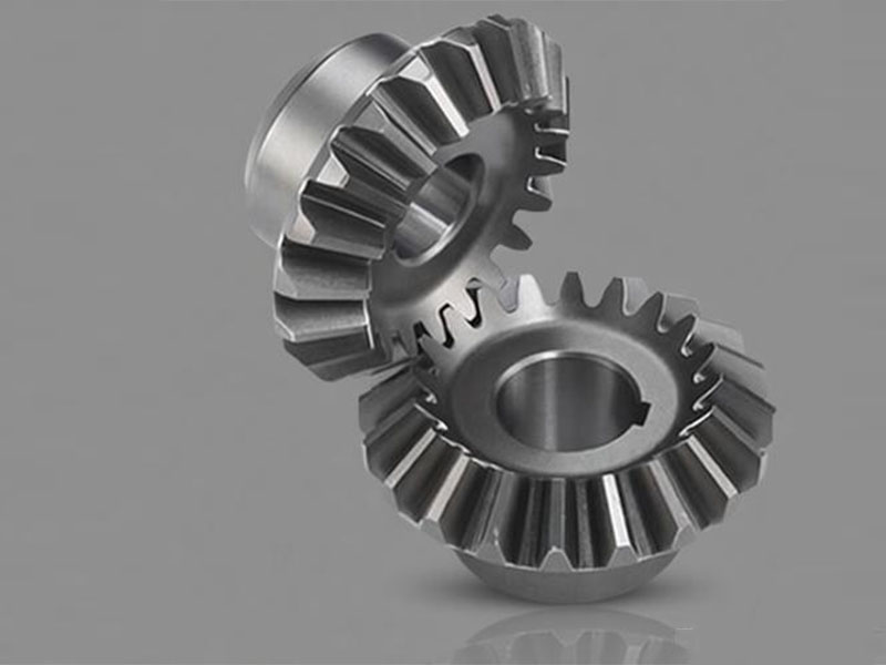 Straight Bevel Gears
- Simple tooth design converging at the apex
- Cost-effective for low-speed applications
- Moderate noise levels
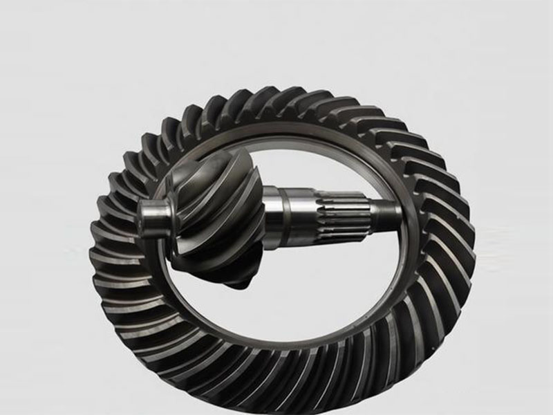
Spiral Bevel Gears
- Curved, helical teeth for gradual engagement
- 30-50% higher load capacity than straight bevel
- Significantly quieter operation
- Preferred for automotive differentials and high-speed applications
Applications of Bevel Gears
- Automotive drive systems
- Marine propulsion
- Power tools
- Industrial angle drives
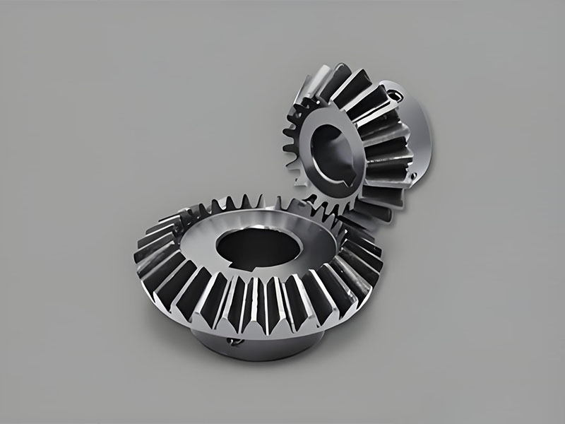
3.2 Miter Gears: The 1:1 Ratio Specialists
Miter gears are a specialized subset of bevel gears where the gear ratio is exactly 1:1. They are designed to transmit power between intersecting shafts—most commonly at a 90-degree angle—with both gears having an equal number of teeth.
 Design and Implementation
- Equal Tooth Count: Both gears in a miter set are identical in size and tooth number, making them interchangeable in many designs.
- Available in Both Straight and Spiral Configurations:
- Straight Miter Gears: Offer a cost-effective solution for low-speed, manual, or intermittent-duty applications where noise is not a primary concern.
- Spiral Miter Gears: Feature curved, helical teeth that engage more gradually. This design provides smoother, quieter operation and higher load capacity, making them suitable for continuous-duty or high-speed applications.
Key Features
- Directional Change: Primarily used to change the axis of rotation without altering speed or torque.
- Compact Design: Provide a compact right-angle drive solution.
- Interchangeability: In many standard designs, the gears are manufactured as matched sets but are mechanically identical.
Common Applications
- Manual Hand Cranks: Used in industrial hand wheels and valve actuators
- to change the operating direction.
- Printing Presses: For synchronizing rollers at right angles.
- Packaging Machinery: To route power around corners in conveyor systems.
- Power Take-Off (PTO) Shafts: On agricultural and industrial equipment where a simple 1:1 turn is needed.
- Robotic Joints: In certain simplified articulated arms requiring precise right-angle motion.
When to Choose Miter Gears
Choose miter gears when your application specifically requires:
- A 1:1 speed ratio
- A change in shaft direction (typically 90°)
- A compact, straightforward solution without the complexity of gear reduction
4. Non-Parallel, Non-Intersecting Shaft Gears
Worm Gears: High Reduction and Self-Locking Capability
 Key Principles
Worm gear systems consist of a threaded worm (screw) meshing with a worm wheel, transmitting power between perpendicular, non-intersecting shafts. Each worm rotation advances the wheel by one tooth (for single-start worms).
Performance Characteristics
- High Reduction Ratios: Achieve ratios from 5:1 to 100:1 in a single stage
- Self-Locking: Prevents back-driving when properly designed
- Compact Design: Maximum reduction in minimal space
- Efficiency Trade-off: Lower efficiency (50-90%) due to sliding friction
Critical Applications
- Elevator and hoist systems requiring safety
- Conveyor systems with backstop requirements
- Automotive steering mechanisms
- Packaging machinery
- Material handling equipment
5. Other Common Gear Types and Applications
5.1 Ratchet Mechanisms: Controlled Unidirectional Motion
 Key Components
- Ratchet wheel with asymmetrical teeth
- Pawl that engages tooth spaces
- Spring to maintain pawl contact
Function
Ratchet mechanisms permit motion in one direction while preventing reverse movement, essential for safety and indexing applications.
Applications
- Jacks and hoists
- Hand tools
- Indexing tables
- Conveyor backstops
5.2 Planetary Gear Sets: Maximum Power Density
Structural Configuration
- Planetary gear sets comprise:
- Sun Gear: Center component
- Planet Gears: Multiple gears mounted on a carrier
- Ring Gear: Outer housing with internal teeth
Performance Advantages
- Exceptional Power Density: 50% space savings compared to conventional designs
- Load Distribution: Multiple planet gears share the load
- Versatile Ratios: Multiple speed ratios from one compact assembly
- Coaxial Arrangement: Input and output on same axis
Industrial Applications
- Automatic transmissions
- Wind turbine pitch and yaw systems
- Industrial robots
- Aerospace actuators
- Heavy equipment final drives
5.3 Rack and Pinion Systems: Rotary to Linear Motion
Core Components
- Pinion: Rotating gear
- Rack: Straight bar with gear teeth
Why Rack and Pinion Excels
- Exceptional Responsiveness: Direct mechanical connection
- Superior Positioning Accuracy: Micron-level precision with proper control
- Long-Distance Power Transmission: Efficient linear motion over extended travel
- Simple Construction: Reliable with minimal maintenance
Applications
- Automotive steering systems
- CNC machine axes
- Automated assembly lines
- 3D printers
- Industrial positioning systems
6. How to Select the Right Gear
6.1 Gear Selection Matrix
| Primary Requirement | Recommended Gear Type | Primary Rationale |
| Minimum Cost / Simplicity | Spur Gears | Simplest design, most economical manufacturing |
| Quiet/Smooth Operation | Helical / Herringbone Gears | Gradual tooth engagement eliminates noise |
| High Reduction in Minimal Space | Worm / Planetary Gears | Maximum ratio in compact envelope |
| Angular Transmission | Spiral Bevel Gears | Smooth 90° power transfer at high efficiency |
| Maximum Efficiency | Spur / Helical Gears | Minimal friction losses (95%+ efficiency) |
| Rotary to Linear Motion | Rack and Pinion | Direct, precise, and efficient conversion |
| Backstop / Anti-Reverse | Worm Gear / Ratchet | Mechanical prevention of reverse motion |
6.2 Critical Questions for Gear Selection
Torque and Speed Parameters
- What are your input and output requirements?
- Are there peak loads or continuous operation conditions?
- What are the starting and stopping characteristics?
Spatial Constraints
- What are the available envelope dimensions?
- Are there shaft orientation requirements?
- Is weight a limiting factor?
Operational Requirements
- What noise and vibration levels are acceptable?
- What is the duty cycle (continuous vs. intermittent)?
- What are the ambient temperature conditions?
Maintenance Considerations
- What is the expected service life?
- Is regular maintenance accessible?
- What lubrication options are available?
Environmental Factors
- Is there exposure to dust, moisture, or chemicals?
- Are there temperature extremes?
- Are there cleanliness requirements (food, medical)?
6.3 Finalizing Your Gear Design
Material Selection
| Material | Advantages | Typical Applications |
| Steel Alloys | Highest strength, wear resistance | Heavy industrial, automotive |
| Cast Iron | Good strength, vibration damping | Large gears, moderate loads |
| Bronze/Brass | Excellent with worms, corrosion resistant | Worm wheels, marine |
| Plastics/Nylon | Lightweight, self-lubricating, quiet | Light-duty, consumer products |
ISO Precision Standards
Gear accuracy directly impacts performance, noise, and life. ISO 1328 defines accuracy classes from 0 (highest precision) to 12 (lowest). For most industrial applications, classes 6-8 provide optimal balance of performance and cost. High-speed or precision applications may require classes 3-5.
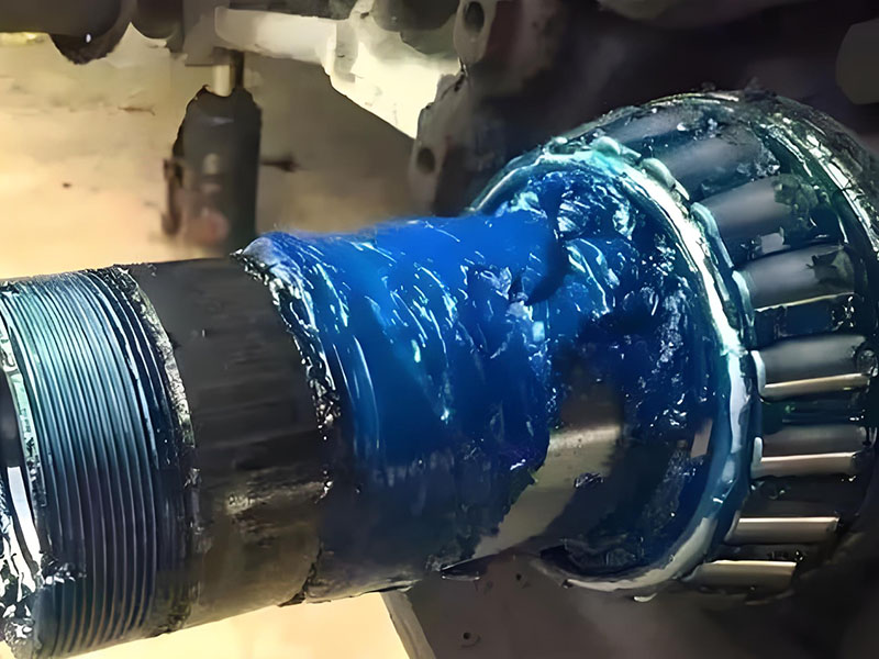
Lubrication Strategy
Proper lubrication is critical for gear longevity:
- Oil Lubrication: Preferred for high-speed, high-temperature applications
- Grease Lubrication: Suitable for enclosed, lower-speed gears
- Splash Lubrication: Common in gearboxes with oil reservoirs
- Forced Circulation: Required for high-power, high-speed systems
- Synthetic Lubricants: Extend service intervals and temperature range
7. Key Criteria for Gear Selection
7.1 Performance Comparison: Load, Efficiency, and Noise
| Gear Type | Load Capacity | Efficiency | Noise Level | Service Life |
| Spur Gears | Moderate | 94-98% | High | Good |
| Helical Gears | High | 93-97% | Low | Excellent |
| Herringbone Gears | Very High | 94-98% | Very Low | Excellent |
| Straight Bevel | Moderate | 93-97% | High | Good |
| Spiral Bevel | High | 94-98% | Low | Excellent |
| Worm Gears | High | 50-90% | Very Low | Good (with proper lube) |
| Planetary | Very High | 95-98% | Low | Excellent |
7.2 Cost, Availability, and Maintenance Evaluation
Initial Investment Considerations
- Simple spur gears offer lowest initial cost
- Precision-ground helical or spiral bevel gears command premium pricing
- Consider total system cost including bearings, housings, and lubrication
Maintenance Requirements
- Open gearing requires regular inspection and lubrication
- Enclosed gearboxes extend maintenance intervals
- Worm gears demand high-quality lubricants and regular changes
- High-precision gears may require professional servicing
Lifecycle Cost Analysis
Look beyond initial purchase price to consider:
- Energy efficiency over operating life
- Maintenance labor and parts
- Downtime costs
- Replacement frequency
7.3 Ensuring Proper Match with Your System
Shaft and Housing Compatibility
- Verify shaft diameters and keyway specifications
- Confirm housing dimensions and mounting provisions
- Check bearing requirements and capacities
Tooth Profile Matching
- Never mix gears with different pressure angles
- Ensure proper module/pitch compatibility
- Verify helix angle matching for helical gears
- Consider backlash requirements for your application
Integration with Existing Components
- Will new gears work with existing bearings and shafts?
- Are lubrication points accessible?
- Does the gear require special seals or shields?
Partner with DUHUI Bearing for Your Gear Solutions
With 20 years of manufacturing experience and 15 years of international export expertise, DUHUI Bearing understands the critical relationship between gears and the bearings that support them. Our engineering team can help you select the optimal gear configuration for your specific application, ensuring compatibility with your bearing systems and operating conditions.
Why Global Customers Choose DUHUI:
- Two decades of precision manufacturing experience
- Comprehensive understanding of international quality standards
- Proven track record with exporters worldwide
- Engineering support for custom applications
- Competitive pricing without compromising quality
Contact our engineering team today for assistance with your gear selection or to discuss your custom requirements. We speak your language—both technically and commercially.