Mounted flange bearings are essential components in modern machinery. They provide a compact, pre-assembled solution for supporting rotating shafts perpendicular to a mounting surface. These units combine a bearing insert with a flanged housing, simplifying installation, reducing downtime, and protecting internal components from contaminants.
However, selecting the wrong configuration leads to premature failure, unplanned downtime, and increased operational costs. With options ranging from 2-bolt to 4-bolt designs, and variations in materials and bearing inserts, making the right choice requires a systematic approach.
DUHUI provides a clear framework for selecting the perfect mounted flange bearing for your specific application.
The DUHUI Selection Framework
Before examining specific bearing types, consider these four critical factors:
- Load: What are the type (radial, axial, moment), direction, and magnitude of forces?
- Environment: What is the operating temperature? Is the unit exposed to moisture, chemicals, or frequent washdowns?
- Shaft: What is the shaft diameter? How will the bearing be locked to it?
- Configuration: Based on the above, what bolt configuration and housing material provide the best support?
Applying this framework ensures a reliable, cost-effective, and long-lasting solution.
Comparing 2, 3, and 4-Bolt Flange Units
The number of mounting bolts is your first indicator of load-handling capability. The flange distributes loads from the bearing to your machine frame, and its design directly determines strength.
2-Bolt Flange Bearings (Diamond Shape – UCFL Series)
The 2-bolt flange, typically diamond-shaped, offers a compact and economical solution. Its two mounting holes align on a single axis running through the bearing center.
- Primary Use: Ideal for light to medium-duty applications where space is limited. Common applications include small conveyors, packaging machinery, and light agricultural equipment.
- Main Risk: Poor resistance to moment loads (forces attempting to tilt the shaft). Because support exists only along a single axis, any significant overhung load can cause flange flexing and bearing misalignment.
- Failure Mode: Premature bearing failure due to misalignment, housing cracking under repeated moment loads, or bolt loosening from vibration.
4-Bolt Flange Bearings (Square Shape – UCF Series)
The 4-bolt square flange serves as the workhorse of heavy industry. With a bolt at each corner, it provides stable, symmetrical mounting support.
- Primary Use: Designed for heavy-duty applications requiring maximum support. Typical applications include large fans, material handling systems, heavy conveyors, and industrial gearboxes.
- Main Risk: Requires a flat and true mounting surface. Any surface irregularity can distort the housing when bolts are torqued, potentially binding the bearing insert.
- Failure Mode: Bearing seizure due to housing distortion, or bolt fatigue failure under extreme dynamic loads.
3-Bolt Flange Bearings (Triangular Shape – UCFT Series)
The 3-bolt flange presents a specialized and often misunderstood design. Two primary types exist: three equally spaced holes (120° apart) and an offset or triangular pattern.
- Primary Use: The 120° pattern offers good symmetrical support. The offset pattern provides solutions for specific spaces, such as tight conveyor corners or where mounting surfaces lack wide channels.
- Installation is Critical: For offset 3-bolt units, orientation determines load capacity. The single lug typically proves weaker. Position the robust side of the triangle to bear the primary load.
- Failure Mode: Installing an offset 3-bolt unit with the single lug in the primary load path leads to rapid lug cracking and complete failure.
Selection Guide: 2-Bolt vs 3-Bolt vs 4-Bolt
The following table summarizes key considerations to guide your initial configuration choice:
| Criteria | 2-Bolt (UCFL) | 3-Bolt (UCFT) | 4-Bolt (UCF) |
| Typical Bore Size | 12 – 50 mm | 20 – 60 mm | 25 – 100+ mm |
| Load Stability | Moderate | Good (Asymmetric) | Excellent |
| Moment Resistance | Low | Moderate | Highest |
| Typical Application | Light-duty, space-constrained | Corner mounts, special brackets | Heavy-duty, high-load |
| Critical Consideration | Avoid for overhung loads | Orientation is everything | Requires flat mounting surface |
Selecting the Right Bearing Insert: Ball vs. Roller
The bearing insert determines friction characteristics and speed capability. This choice depends on the “Load” aspect of the L.E.S.C. framework.
Ball Bearing Inserts
Ball bearings represent the most common insert type. They use spherical rolling elements and are designed for high-speed operation while accommodating both radial and light axial (thrust) loads.
Ball bearing inserts serve as the default choice for applications such as electric motors and light-duty conveyors where speeds range from moderate to high and loads remain predictable.
Roller Bearing Inserts
Applications involving heavy radial loads, shock loads, or larger shaft diameters require roller bearing inserts. Spherical roller bearings excel at handling misalignment and heavy loads, making them ideal for aggregate processing or heavy forestry equipment.
The trade-off involves lower maximum speed compared to ball bearings.
Bearing-to-Shaft Locking Methods
After selecting the insert, you must determine how to lock it to the shaft. This addresses the “Shaft” component of the L.E.S.C. framework.
- Setscrew Locking: The most common and economical method. Setscrews in the inner ring tighten directly onto the shaft. Best for moderate loads and bidirectional thrust applications.
- Eccentric Locking Collar: A cam-action collar tightens the bearing onto the shaft. Good for reversing loads but may cause slight shaft runout if installation is not precise.
- Concentric Locking Collar: Provides the most precise and secure fit by clamping the inner ring evenly around the shaft circumference. Ideal for high-precision applications like CNC spindles or fans.
Critical Material Selection for Harsh Environments
The housing material serves as your bearing’s first defense against the “Environment” in the L.E.S.C. framework. Incorrect material selection invites corrosion or mechanical failure.
Housing Material Comparison
The following table compares common housing materials to help match material to operating conditions:
| Material | Temperature Range | Corrosion Resistance | Impact Strength | Relative Cost |
| Cast Iron (GG-25) | -20°C to 200°C | Poor (rust-prone) | Moderate | 1.0x (baseline) |
| Ductile Iron (GGG-40) | -20°C to 250°C | Poor | High (fracture-resistant) | 1.3x |
| Stainless Steel (304) | -40°C to 300°C | Excellent | High | 3.5x |
| Thermoplastic (PPS) | -10°C to 120°C | Excellent (chemical) | Low (creep risk) | 2.5x |
Application-Specific Selection Guide
Cast Iron serves as the standard for most industrial applications in dry, indoor environments. It offers excellent vibration damping at low cost.
Ductile Iron should be specified where shock loads or vibration prove extreme, such as in rock crushers or shredders. Its higher strength prevents catastrophic housing fracture.
Stainless Steel becomes mandatory for food processing, pharmaceutical, marine, and chemical applications. It withstands frequent washdowns and corrosive agents.
Thermoplastic provides an excellent choice for sterile environments or where contact with harsh chemicals is expected. It is lightweight, rust-proof, but cannot handle heavy loads.
When Stainless Steel is Non-Negotiable
While more expensive, stainless steel represents the only appropriate choice when:
- Compliance: You must meet FDA or USDA sanitary standards
- Contamination Risk: Rust particles from cast iron could contaminate products (food, pharmaceuticals, electronics)
- Corrosion is Certain: Marine environments or exposure to acids and bases
- High Temperature + Humidity: This combination rapidly destroys standard cast iron
Cost Rationalization
While stainless steel costs approximately 3.5 times more than cast iron, consider the total cost of ownership. In food processing applications, one hour of unplanned downtime due to bearing failure can cost thousands of dollars in lost production and wasted product. The initial investment in proper materials prevents these losses.
Best Installation and Maintenance Practices
Even correctly selected bearings fail early without proper installation and maintenance.
Pre-Installation Checks
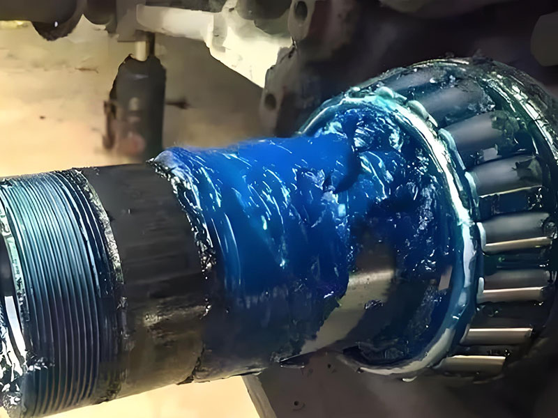
Seal Integrity: Inspect seals for shipping damage. A compromised seal creates a direct contamination path.
Mounting Surface: Ensure the surface is flat, clean, and free of burrs. For 4-bolt units, this proves critical to prevent housing distortion.
Shaft Alignment: Roughly align the shaft to the bearing bore before tightening any bolts.
Proper Mounting Procedure
Always use a torque wrench to tighten all flange bolts evenly in a star pattern. This ensures even load distribution, prevents housing distortion, and provides maximum clamping force to resist vibration.
Refer to manufacturer specifications for correct torque values.
The Torque-Tension Relationship
Understanding the torque-tension relationship proves essential. Bolt torque directly determines clamping force. Under-torquing allows movement and fretting corrosion. Over-torquing can crack housings or strip threads.
Predictive Maintenance Data Points
Establish baseline measurements and monitor these indicators:
Vibration Analysis: Sudden vibration increases often indicate bearing raceway damage or imbalance.
Temperature Monitoring: Steady temperature rises above baseline can signal over-lubrication, misalignment, or failing components.
Conclusion
Selecting the correct mounted flange bearing involves multiple engineering decisions beyond simple shaft size matching. By applying the DUHUI L.E.S.C. Selection Framework—evaluating Load, Environment, Shaft locking, and Configuration—you can systematically narrow thousands of options to the perfect choice for your machinery.
Begin by determining required load stability to choose between 2, 3, and 4-bolt configurations. Match the bearing insert and locking method to your speed and precision requirements. Finally, protect your investment by selecting housing material engineered for your specific operating environment.